
Gl glasslink hardware

About the Gl glasslink hardware PCB
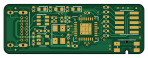
Gl glasslink hardware is an open source PCB design by glassboard-dev, published on GitHub under the CC-BY-SA-4.0 license. It is a 2-layer board measuring 37 × 13 mm, with 34 components from 18 distinct parts.
Other key parts include the SN65220, AP2204K-3.3 and LPC11U35FHI33_501. By type, the board carries 16 resistors, 8 capacitors, 3 ICs, 3 diodes, 2 connectors and 1 crystal.
It belongs with the usb & debug tools designs in this gallery.
From the project
DAPLink (CMSIS-DAP) compatible hardware
Once you are ready to flash firmware to the DAPLink hardware, you can utilize the built-in NXP USB ROM Bootloader. A fresh piece of hardware should enumerate immediately into the bootloader when the USB is plugged in. Otherwise, you can hold down the pushbutton while plugging in the USB. The ROM Bootloader will enumerate as a MSD labeled .
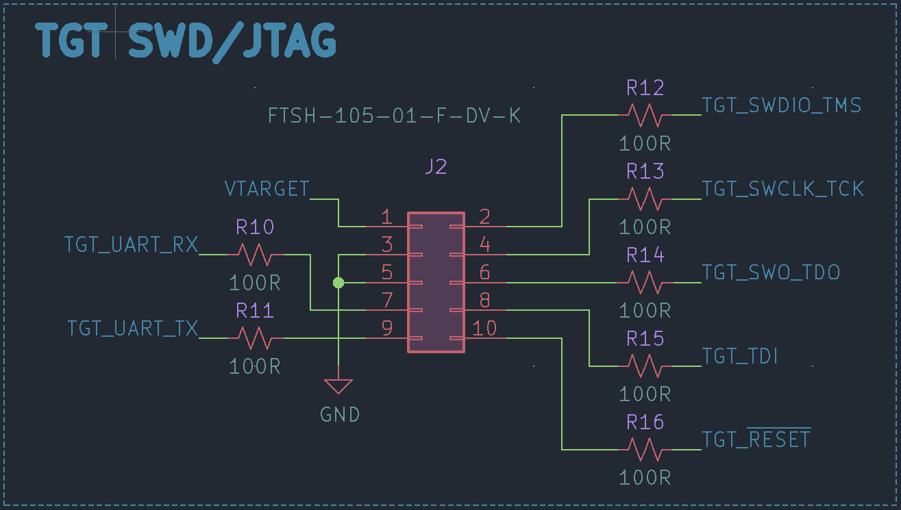
To connect the Glasslink serial lines to your targets UART, please reference the 10pin ARM header pinout below. The current design assumes that you are creating your target hardware and have the ability to route your UART pins to the "unused" pins of the…
Main components on the Gl glasslink hardware
Gl glasslink hardware bill of materials (BOM)
34 components, 18 distinct parts.
| Qty | Part | Footprint | Refs |
|---|---|---|---|
| 1 | SN65220 | SOT-23-6 | U1 |
| 1 | AP2204K-3.3 | SOT-23-5 | U2 |
| 1 | LPC11U35FHI33_501 | QFN-32_EP_6.2x6.2_Pitch0.5mm | U3 |
| 1 | ECS-120-20-30B-TR | Crystal_SMD_5032-4Pin_5.0x3.2mm | Y1 |
| 1 | USB_C_Receptacle_USB2.0 | USB_C_Receptacle_GCT_USB4085 | J1 |
| 1 | FTSH-105-01-F-DV-K | PinHeader_2x05_P1.27mm_Vertical_SMD | J2 |
| 1 | SW_Push | Panasonic_EVQPUL_EVQPUC | SW1 |
| 1 | RED | LED_0603_1608Metric | D1 |
| 1 | BLUE | LED_0603_1608Metric | D2 |
| 1 | GREEN | LED_0603_1608Metric | D3 |
| 2 | 20p | C_0402_1005Metric | C1, C2 |
| 2 | 10u | C_0402_1005Metric | C3, C7 |
| 4 | 0.1u | C_0402_1005Metric | C4, C5, C6, C8 |
| 3 | 10k | R_0402_1005Metric | R1, R2, R9 |
| 3 | 470R | R_0402_1005Metric | R3, R4, R5 |
| 2 | 22R | R_0402_1005Metric | R6, R7 |
| 1 | 1.5k | R_0402_1005Metric | R8 |
| 7 | 100R | R_0402_1005Metric | R10, R11, R12, R13, R14, R15, R16 |
Gl glasslink hardware design files
The KiCad project lives in the glassboard-dev/gl-glasslink-hardware repository on GitHub; these links point at the commit this page was built from.
- LayoutGlassLink.kicad_pcb
Gl glasslink hardware: common questions
How big is the Gl glasslink hardware PCB?
The Gl glasslink hardware measures 37 × 13 mm, has 2 copper layers and is 1.6 mm thick.
How many components are on the Gl glasslink hardware?
34 components, from 18 distinct parts. The full bill of materials is listed on this page.
Where can I download the Gl glasslink hardware design files?
From the glassboard-dev/gl-glasslink-hardware repository on GitHub, which has the KiCad layout; the links under Design files point to each one.
Can I use the Gl glasslink hardware design in my own project?
Yes, under the terms of its CC-BY-SA-4.0 license, which glassboard-dev chose for the repository.
Similar boards
XG Station Power
osy
54.3 × 91 mm9 parts2LCC-BY-4.0703
USB Hub Test
50 × 50 mm85 parts4LCC-BY-4.0703
FW-EC-DongleHiderPlus
LeoDJ
28.2 × 26.1 mm14 parts4LCERN-OHL-W-2.0490
Adapter tsop48
bbogush
48 × 33 mm3 parts2LGPL-3.0389
Adapter tsop48 solder
48 × 33 mm3 parts2LGPL-3.0389
Adapter soic8 solder
48 × 20 mm3 parts2LGPL-3.0389