
T4-MFA

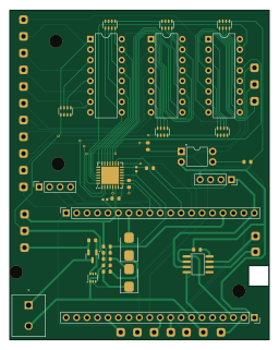
About the T4-MFA PCB
T4-MFA is an open source PCB design by gmoccapy, published on GitHub. It is a 2-layer board measuring 63 × 80 mm, with 41 components from 27 distinct parts.
Other key parts include the LTV-847, EL817(B)-F, SN65HVD230DR and MCP23017_ML. By type, the board carries 18 resistors, 6 ICs, 3 relays, 2 transistors, 2 connectors and 2 diodes.
From the project
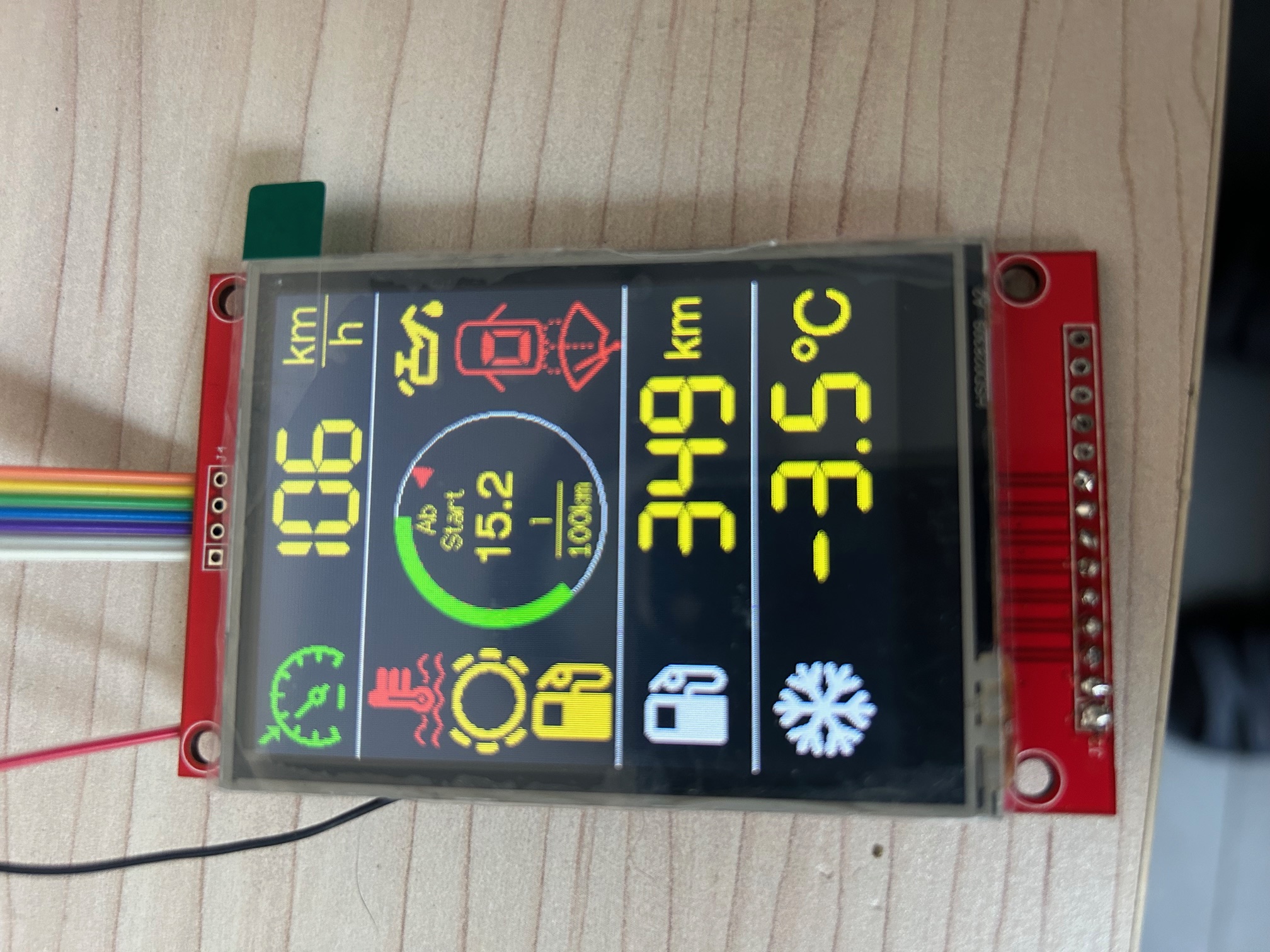
This is a color MFA designed to be used in a Volkswagen T4 Van
T4-MFA is a projekt to customize the Dash Board from an Volkswagen T4 Van with a color MFA (Multi Function Diaplay)
It is based on a ESP32S-Dev Kit C V4 with 512 kB SRAM and 4 MB Flash The used display is an 3,5 Inch RPI Display with 480x320 Pixel The connections from the display need to be modified The CAN connections are done with a WCMCU-230 Modul (R2 has to be removed) Power Control is solved with a 12V USB Car Adapter (the mainboard from the adapter has been used) The connections are done to a self desgned brake out board Some soldering on the Dash Board Instrument has to be done
Main components on the T4-MFA
T4-MFA bill of materials (BOM)
41 components, 27 distinct parts — part numbers from the project's BOM.
| Qty | Part | Footprint | Refs |
|---|---|---|---|
| 3 | LTV-847 | DIP-16_W7.62mm | U1, U2, U3 |
| 1 | EL817(B)-F EVERLIGHT(亿光) | DIP-4_L6.5-W4.6-P2.54-LS7.6-BL-1 | U4 |
| 1 | SN65HVD230DR Texas Instruments | SOIC-8_L4.9-W3.9-P1.27-LS6.0-BL | U5 |
| 1 | MCP23017_ML | QFN-28-1EP_6x6mm_P0.65mm_EP4.25x4.25mm | U6 |
| 1 | LBSS84LT1G LRC | Q_SOT-23 | Q1 |
| 1 | MMDT3904 | SOT-363_SC-70-6 | Q2 |
| 2 | CONN_01X19_SOCKET Conn_01x19_Socket | PinSocket_1x19_P2.54mm_Vertical | J1, J2 |
| 1 | TFT_5V | SolderWire-0.5sqmm_1x01_D0.9mm_OD2.1mm | 5V |
| 1 | BME280_conn | PinSocket_1x04_P2.54mm_Vertical | BME_280 |
| 1 | K31 | SolderWire-0.5sqmm_1x01_D0.9mm_OD2.1mm | K3 |
| 1 | K15 | SolderWire-0.5sqmm_1x01_D0.9mm_OD2.1mm | K15 |
| 1 | K30 | SolderWire-0.5sqmm_1x01_D0.9mm_OD2.1mm | K30 |
| 1 | Memory | SolderWire-0.5sqmm_1x01_D0.9mm_OD2.1mm | MEM1 |
| 1 | Mode | SolderWire-0.5sqmm_1x01_D0.9mm_OD2.1mm | MODE1 |
| 1 | Reset | SolderWire-0.5sqmm_1x01_D0.9mm_OD2.1mm | RESET1 |
| 1 | To USB converter | PHOENIX_1729128_2x2,54 | USB_OUT1 |
| 2 | S3MB hongjiacheng | D_SMB | D1, D2 |
| 2 | 100NF 100nF Samsung Electro-Mechanics | C_0402 | C1, C2 |
| 4 | 10kΩ UNI-ROYAL(Uniroyal Elec) | R_0603 | R1, R14, R15, R16 |
| 1 | 220kΩ UNI-ROYAL(Uniroyal Elec) | R_0603 | R2 |
Show 7 more
| Qty | Part | Footprint | Refs |
|---|---|---|---|
| 2 | 100kΩ UNI-ROYAL(Uniroyal Elec) | R_0603 | R3, R5 |
| 1 | 33kΩ UNI-ROYAL(Uniroyal Elec) | R_0603 | R4 |
| 1 | 220Ω UNI-ROYAL(Uniroyal Elec) | R_0603 | R6 |
| 3 | 4.7kΩ UNI-ROYAL(Uniroyal Elec) | R_0603x4 | R7, R8, R11 |
| 3 | 10kΩ UNI-ROYAL(Uniroyal Elec) | R_0603x4 | R9, R10, R13 |
| 1 | 4.7kΩ UNI-ROYAL(Uniroyal Elec) | R_0603 | R12 |
| 2 | C25804 4,7k UNI-ROYAL(Uniroyal Elec) | R_0603 | R17, R18 |
T4-MFA design files
The KiCad project lives in the gmoccapy/T4-MFA repository on GitHub; these links point at the commit this page was built from.
T4-MFA: common questions
How big is the T4-MFA PCB?
The T4-MFA measures 63 × 80 mm, has 2 copper layers and is 1.6 mm thick.
How many components are on the T4-MFA?
41 components, from 27 distinct parts, with part numbers taken from the project's own BOM. The full bill of materials is listed on this page.
Where can I download the T4-MFA design files?
From the gmoccapy/T4-MFA repository on GitHub, which has the KiCad layout, the schematic and the BOM; the links under Design files point to each one.
Can I use the T4-MFA design in my own project?
The repository has no license, so all rights stay with gmoccapy. Use it as a reference, and ask the author before reusing the design.