
Bolty mood module

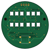
About the Bolty mood module
Bolty mood module is an open source AVR/Arduino PCB design by haadmahboob, published on GitHub. It is a 2-layer board measuring 40 × 40 mm, with 32 components from 14 distinct parts.
Its main chip is the ATTINY85-20SU, from the AVR/Arduino family. By type, the board carries 13 diodes, 8 capacitors, 5 resistors, 2 connectors, 1 IC and 1 transistor.
It belongs with the robotics & motion designs in this gallery.
From the project
40 mm round ATtiny85 robot face PCB: 12 RGB LEDs, buzzer, button, I2C 0x42 (KiCad 10)
A 40 mm round, 2-layer PCB that gives the Bolty robot a face. An ATtiny85 drives two 3×2 "eyes" made of 12 reverse-mount SK6812MINI-E RGB LEDs, plus a buzzer and a pat button. The main robot sets the mood over I2C at address 0x42.
- [x] Schematic (ERC clean) - [x] PCB layout and routing (DRC: 0 errors, 0 unconnected, 0 schematic mismatches) - [x] Fabrication files and BOM - [ ] PCBs ordered - [ ] Assembled and tested
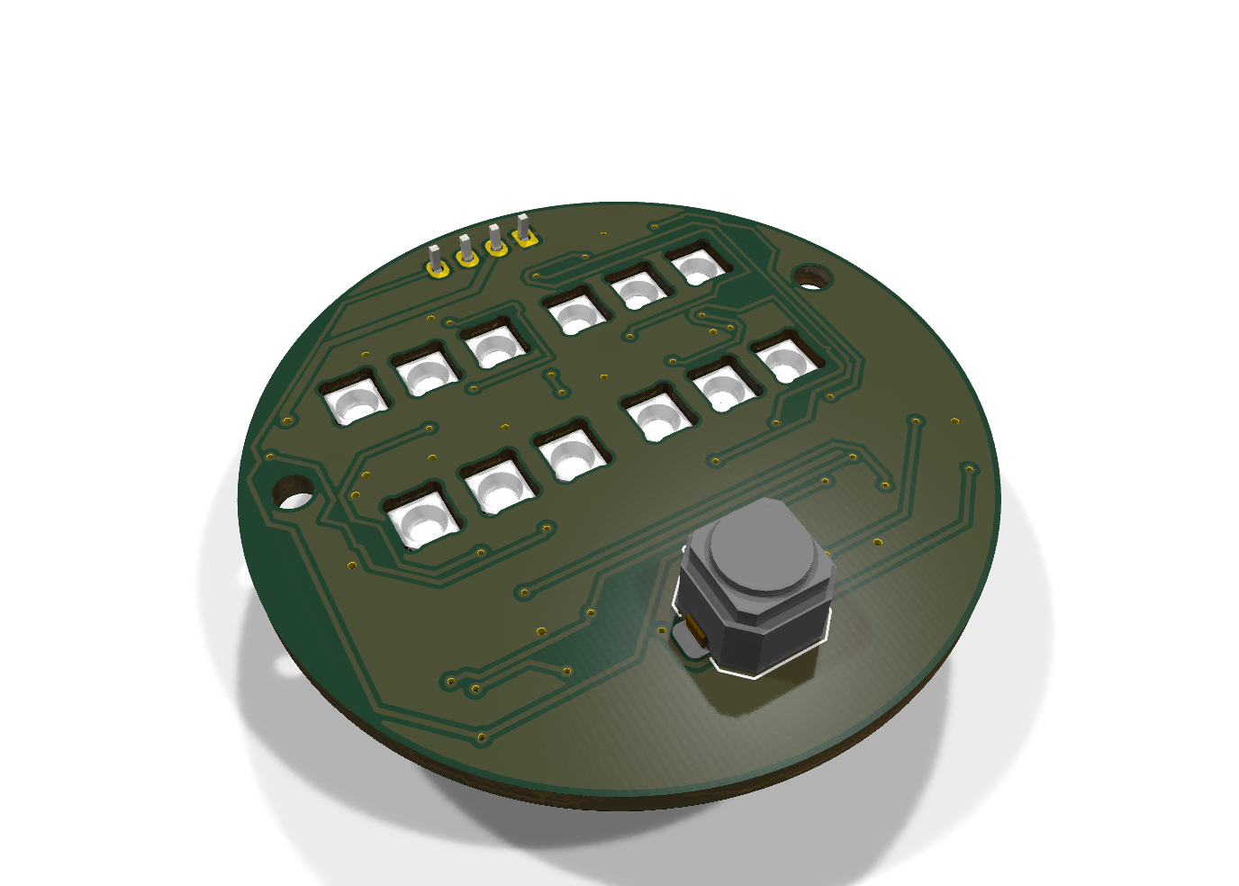
Main components on the Bolty mood module
Bolty mood module bill of materials (BOM)
32 components, 14 distinct parts — part numbers from the project's BOM.
| Qty | Part | Footprint | Refs |
|---|---|---|---|
| 1 | ATTINY85-20SU ATtiny85-20SU Microchip | SOIC-8_5.3x5.3mm_P1.27mm | U1 |
| 1 | MMBT3904LT1G MMBT3904 onsemi | SOT-23 | Q1 |
| 1 | B4B-PH-K-S(LF)(SN) I2C (JST-PH 4) JST | JST_PH_B4B-PH-K_1x04_P2.00mm_Vertical | J1 |
| 1 | ISP | ISP_Pads_2x3_P2.54mm | J2 |
| 1 | CMT-8504-100-SMT-TR CMT-8504-100-SMT Same Sky | MagneticBuzzer_CUI_CMT-8504-100-SMT | BZ1 |
| 1 | PTS645SM43SMTR92 LFS Pat C&K | SW_SPST_PTS645Sx43SMTR92 | SW1 |
| 12 | 4960 SK6812MINI-E Adafruit | LED_SK6812MINI-E_3.2x2.8mm_P1.5mm_ReverseMount | D1, D2, D3, D4, D5, D6, D7, D8 +4 |
| 1 | 1N4148W-7-F 1N4148W Diodes Inc. | D_SOD-123 | D13 |
| 1 | CL21A106KAYNNNE 10u Samsung | C_0805_2012Metric | C1 |
| 7 | CL10B104KB8NNNC 100n Samsung | C_0603_1608Metric | C2, C3, C4, C5, C6, C7, C8 |
| 1 | RC0603FR-0710KL 10k Yageo | R_0603_1608Metric | R1 |
| 1 | RC0603FR-071KL 1k Yageo | R_0603_1608Metric | R2 |
| 1 | RC0603FR-07330RL 330 Yageo | R_0603_1608Metric | R3 |
| 2 | RC0603FR-074K7L 4.7k Yageo | R_0603_1608Metric | R4, R5 |
Bolty mood module design files
The KiCad project lives in the haadmahboob/bolty-mood-module repository on GitHub; these links point at the commit this page was built from.
Bolty mood module: common questions
What microcontroller does the Bolty mood module use?
The Bolty mood module is built around the ATTINY85-20SU, from the AVR/Arduino family.
How big is the Bolty mood module?
The Bolty mood module measures 40 × 40 mm, has 2 copper layers and is 1.6 mm thick.
How many components are on the Bolty mood module?
32 components, from 14 distinct parts, with part numbers taken from the project's own BOM. The full bill of materials is listed on this page.
Where can I download the Bolty mood module design files?
From the haadmahboob/bolty-mood-module repository on GitHub, which has the KiCad layout, the schematic and the BOM; the links under Design files point to each one.
Can I use the Bolty mood module design in my own project?
The repository has no license, so all rights stay with haadmahboob. Use it as a reference, and ask the author before reusing the design.
Can I test firmware for the Bolty mood module without the hardware?
Yes. HardLabs builds a simulation of the board from its netlist and BOM, so you can run and debug AVR/Arduino firmware against it before you order a PCB.
Similar boards
 AVR/Arduino
Magspoof
samyk
35 × 29 mm11 parts2LNo license4.2k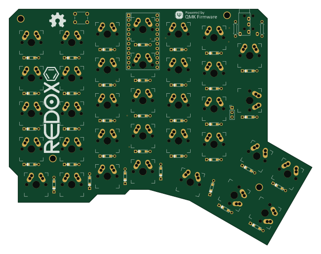 AVR/Arduino
Redox keyboard
mattdibi
162.2 × 126.5 mm77 parts2LMIT2.0k AVR/Arduino
Labrador
espotek-org
36.8 × 34.7 mm75 parts2LNo license1.2k AVR/Arduino
ModuleV450
stuartpittaway
30 × 61.4 mm39 parts2LCC-BY-NC-4.01.1k AVR/Arduino
V4
30 × 50 mm38 parts2LCC-BY-NC-4.01.1k AVR/Arduino
Discipline
coseyfannitutti
304.9 × 122.8 mm170 parts2LCC-BY-NC-4.01.0k