
HenryFlops

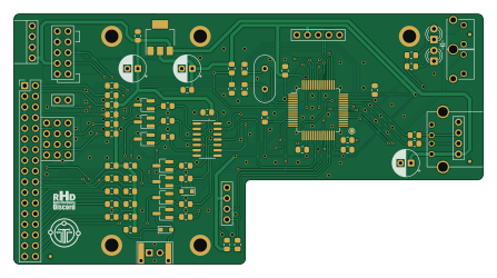
About the HenryFlops PCB
HenryFlops is an open source STM32 PCB design by hmerrett, published on GitHub under the Custom license license. It is a 2-layer board measuring 111.6 × 59.4 mm, with 77 components from 31 distinct parts.
Its main chip is the STM32F105RBT6, from the STM32 family. Other key parts include the 74HCT04 and LM1117-3.3. By type, the board carries 17 resistors, 14 capacitors, 9 connectors, 7 transistors, 3 ICs and 2 switches.
It belongs with the displays & leds designs in this gallery.
From the project
OpenFlops is an Open Hardware implementation of such an emulator, inspired from the ubiquitous Gotek hardware. It is designed to run the FlashFloppy firmware, which gives it several improvements over the original Gotek: - Can be installed on many different platforms - Directly su
OpenFlops is an Open Hardware implementation of such an emulator, inspired from the ubiquitous Gotek hardware. It is designed to run the FlashFloppy firmware, which gives it several improvements over the original Gotek: - Can be installed on many different platforms - Directly supports a wide range of image formats - Flexible track layout for Raw Sector Images - Extremely configurable - Supports AutoSwap for games with a large number of disks - Easily accessible pin headers for connection of a i2c display (either OLED or LCD), rotary encoder (including power) - Built-in amplified speaker, or…

Main components on the HenryFlops
HenryFlops bill of materials (BOM)
77 components, 31 distinct parts — part numbers from the project's BOM.
| Qty | Part | Footprint | Refs |
|---|---|---|---|
| 1 | 74HCT04 | SOIC-14_3.9x8.7mm_P1.27mm | U1 |
| 1 | STM32F105RBT6 | LQFP-64_Handsoldering | U3 |
| 1 | LM1117-3.3 | SOT-223-3_TabPin2 | U4 |
| 6 | BSS138 | SOT-23_Handsoldering | Q1, Q2, Q3, Q4, Q5, Q6 |
| 1 | MMBT3904 | SOT-23_Handsoldering | Q7 |
| 1 | 8 MHz | Crystal_HC49-U_Vertical | Y1 |
| 1 | FLOPPY_CONN | PinHeader_2x17_P2.54mm_Vertical | P1 |
| 1 | POWER_INPUT | PinHeader_1x04_P2.54mm_Vertical | P2 |
| 1 | USB_A_FEMALE | USB_A_FEMALE | P3 |
| 1 | PROG_PORT | PinHeader_2x05_P2.54mm_Vertical | P4 |
| 1 | JUMPER_JC | PinHeader_1x02_P2.54mm_Vertical | P5 |
| 1 | ENCODER_PORT | PinHeader_1x05_P2.54mm_Vertical | P6 |
| 1 | DISPLAY_PORT | PinHeader_1x04_P2.54mm_Vertical | P7 |
| 1 | USB_HEADER | PinHeader_1x04_P2.54mm_Vertical | P8 |
| 1 | EXTERNAL_SPEAKER | PinHeader_1x02_P2.54mm_Mute | P9 |
| 4 | Conn_01x03 | PinHeader_1x03_P2.54mm_Mute | PA5, PB5, PC5, PD5 |
| 15 | 1k | R_0805_2012Metric_Pad1.15x1.40mm_HandSolder | PU1, PU2, PU3, PU4, PU5, PU6, PU7, PU8 +7 |
| 1 | BT_RIGHT | PUSH_BUTTON_RIGHT_ANGLE | S3 |
| 1 | BT_LEFT | PUSH_BUTTON_RIGHT_ANGLE | S4 |
| 1 | Speaker | Buzzer | SPK1 |
Show 11 more
| Qty | Part | Footprint | Refs |
|---|---|---|---|
| 1 | LED_GREEN | LED_D3.0mm | LD1 |
| 1 | LED_RED | LED_D3.0mm | LD2 |
| 2 | 1N4148 | D_SOD-323_HandSoldering | D1, D2 |
| 1 | 100u | CP_Radial_D6.3mm_P2.50mm | C1 |
| 2 | 22P 22p | C_0805_2012Metric_Pad1.15x1.40mm_HandSolder | C3, C5 |
| 9 | 100N 100n | C_0805_2012Metric_Pad1.15x1.40mm_HandSolder | C4, C6, C7, C8, C9, C10, C18, C20 +1 |
| 2 | 10u | CP_Radial_D6.3mm_P2.50mm | C17, C19 |
| 3 | 22 | R_0805_2012Metric_Pad1.15x1.40mm_HandSolder | R1, R2, R6 |
| 2 | 3.3K | R_0805_2012Metric_Pad1.15x1.40mm_HandSolder | R3, R4 |
| 9 | 1k | R_0805_2012Metric_Pad1.15x1.40mm_HandSolder | R5, R20, R21, RN1, RN2, RN3, RN4, RN5 +1 |
| 3 | 4K7 4k7 | R_0805_2012Metric_Pad1.15x1.40mm_HandSolder | R7, R10, R13 |
HenryFlops design files
The KiCad project lives in the hmerrett/HenryFlops repository on GitHub; these links point at the commit this page was built from.
HenryFlops: common questions
What microcontroller does the HenryFlops use?
The HenryFlops is built around the STM32F105RBT6, from the STM32 family.
How big is the HenryFlops PCB?
The HenryFlops measures 111.6 × 59.4 mm, has 2 copper layers and is 1.6 mm thick.
How many components are on the HenryFlops?
77 components, from 31 distinct parts, with part numbers taken from the project's own BOM. The full bill of materials is listed on this page.
Where can I download the HenryFlops design files?
From the hmerrett/HenryFlops repository on GitHub, which has the KiCad layout, the schematic and the BOM; the links under Design files point to each one.
Can I use the HenryFlops design in my own project?
It is published under Custom license, which limits how it may be reused; read the license before building on it.
Can I test firmware for the HenryFlops without the hardware?
Yes. HardLabs builds a simulation of the board from its netlist and BOM, so you can run and debug STM32 firmware against it before you order a PCB.
Similar boards
 STM32
STM32AxxSolder
AxxAxx
39 × 82.5 mm122 parts2LGPL-3.01.7k STM32
STM32AIOC
skuep
21 × 31.5 mm47 parts2LMIT1.4k STM32
STM32Ferris
pierrechevalier83
208.8 × 86.8 mm102 parts2LSHL-2.11.3k STM32
STM32Module 16S
stuartpittaway
71.1 × 89.6 mm113 parts4LCC-BY-NC-4.01.1k STM32
STM32Djinn
tzarc
192.3 × 150.5 mm216 parts2LCERN-OHL-S-2.0988 STM32
STM32Ghoul
228.6 × 79.4 mm163 parts2LCERN-OHL-S-2.0988