
Inductor tester

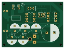
About the Inductor tester PCB
Inductor tester is an open source PCB design by ikatkov, published on GitHub. It is a 4-layer board measuring 62.5 × 46.2 mm, with 31 components from 22 distinct parts.
Other key parts include the NE555P. By type, the board carries 14 capacitors, 6 connectors, 4 resistors, 2 ICs, 2 diodes and 1 transistor.
It belongs with the test & measurement designs in this gallery.
From the project
Power) Inductor saturation current tester
~60A max current. Power supply 5-25V. Based on http://elm-chan.org/works/lchk/report.html
You will need an oscilloscope to take measurements.
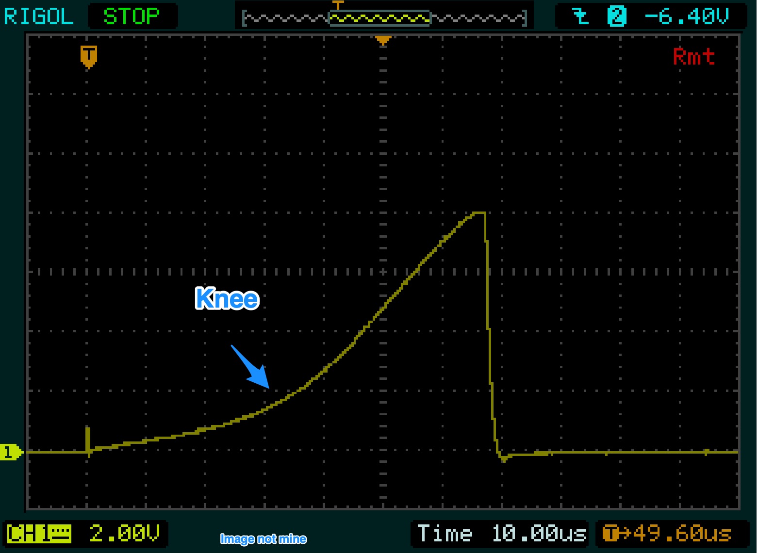
Once powered, the capacitor bank charges up. The circuit fires off a variable-width pulse into the MOSFET gate. MOSFET turns ON and short-circuits the inductor to the capacitor power bank. The current starts to rise linearly until the saturation point is reached. Once the inductor is saturated, it behaves like an ohmic piece of wire, and the current increases exponentially until the pulse is over, and the MOSFET is switched OFF. Saturation is a knee…
Main components on the Inductor tester
Inductor tester bill of materials (BOM)
31 components, 22 distinct parts.
| Qty | Part | Footprint | Refs |
|---|---|---|---|
| 2 | NE555P | DIP-8_W7.62mm | U1, U2 |
| 1 | T60NO2R | TO-252-2 | Q1 |
| 2 | inductor connector | SolderWirePad_1x01_SMD_2x4mm | J1, J2 |
| 2 | test point | PinHeader_1x02_P2.54mm_Vertical | J3, J4 |
| 1 | IN | BarrelJack_Horizontal | J5 |
| 1 | pulse width selector | PinHeader_2x03_P2.54mm_Vertical | J6 |
| 1 | 2A | R_2512_6332Metric | F1 |
| 1 | 100k | Potentiometer_Bourns_3296W_Vertical | RV1 |
| 1 | SS34 | D_SMA | D1 |
| 1 | 1N4001 | D_MELF | D2 |
| 2 | 100nF | C_1206_3216Metric | C1, C12 |
| 2 | 10nF | C_1206_3216Metric | C2, C14 |
| 2 | 470uF | CP_Radial_D10.0mm_P5.00mm | C3, C11 |
| 3 | 220uF | CP_Radial_D10.0mm_P5.00mm | C4, C5, C6 |
| 1 | 4700u | CP_Radial_D18.0mm_P7.50mm | C7 |
| 1 | 470pF | C_1206_3216Metric | C8 |
| 2 | optional | C_1206_3216Metric | C9, C10 |
| 1 | 220nF | C_1206_3216Metric | C13 |
| 1 | 2.2M | R_0805_2012Metric | R1 |
| 1 | 2.2k | R_0805_2012Metric | R3 |
Show 2 more
| Qty | Part | Footprint | Refs |
|---|---|---|---|
| 1 | 100m | R_2512_6332Metric | R4 |
| 1 | 62 | R_0805_2012Metric | R5 |
Inductor tester design files
The KiCad project lives in the ikatkov/inductor-tester repository on GitHub; these links point at the commit this page was built from.
- Layoutmain.kicad_pcb
- Schematicmain.kicad_sch
Inductor tester: common questions
How big is the Inductor tester PCB?
The Inductor tester measures 62.5 × 46.2 mm, has 4 copper layers and is 1.6 mm thick.
How many components are on the Inductor tester?
31 components, from 22 distinct parts. The full bill of materials is listed on this page.
Where can I download the Inductor tester design files?
From the ikatkov/inductor-tester repository on GitHub, which has the KiCad layout and the schematic; the links under Design files point to each one.
Can I use the Inductor tester design in my own project?
The repository has no license, so all rights stay with ikatkov. Use it as a reference, and ask the author before reusing the design.
Similar boards
LevelShifter
gusmanb
28.3 × 39.8 mm21 parts2LGPL-3.05.0k
StackLink
52.3 × 10.5 mm5 parts2LGPL-3.05.0k
AnalyzerBoxPCB fork
52.7 × 47.9 mm54 parts4LGPL-3.05.0k
EleLab v2 Bus100
Chrismettal
100 × 100 mm37 parts2LGPL-3.0528
EleLab v2 Bus150
150 × 50 mm37 parts2LGPL-3.0528
EleLab v2 PowerFeed
68 × 50 mm11 parts2LGPL-3.0528