
Flight-Computer

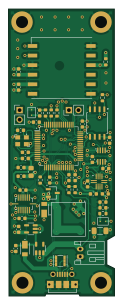
About the Flight-Computer PCB
Flight-Computer is an open source STM32 PCB design by ImperialSpaceSociety, published on GitHub. It is a 4-layer board measuring 28.1 × 76.1 mm, with 57 components from 31 distinct parts.
Its main chip is the STM32F446RET6, from the STM32 family. Other key parts include the W25Q64JVSS 64MBit Flash Chip, SDR08540M3-01 SMD Buzzer, BME280 Environment Sensor, STF202-22T1G ESD/EMI Chip and MAX40203_SOT23 Ideal Diode. By type, the board carries 25 capacitors, 12 ICs, 9 resistors, 5 connectors, 4 diodes and 1 crystal.
It belongs with the sensors and rf & radio designs in this gallery, and the repository also holds 1 earlier revision of it.
From the project
HPR project by undergraduate students from Imperial College Space Society.
The rocket was initially designed in a program called OpenRocket and then the particular components were designed in Fusion 360 and manufactured using 3D printers or a laser cutter.
The flight computer is based on STM32 platform and the main diagram with its components can be seen below.
The following picture shows the 3D render of the flight computer designed in KiCAD.
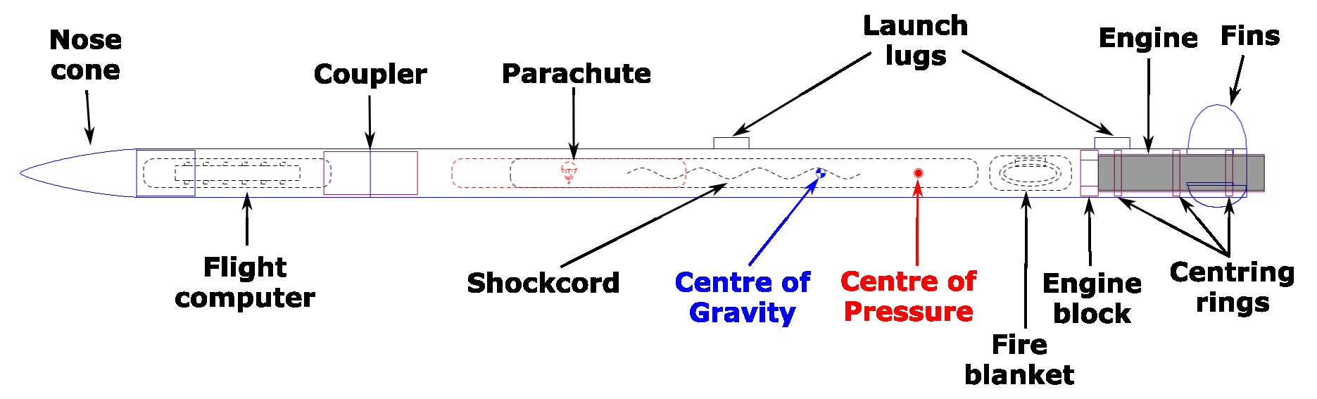
Main components on the Flight-Computer
Flight-Computer bill of materials (BOM)
57 components, 31 distinct parts — part numbers from the project's BOM.
| Qty | Part | Footprint | Refs |
|---|---|---|---|
| 1 | STM32F446RET6 | LQFP-64_10x10mm_P0.5mm | U1 |
| 1 | W25Q64JVSS 64MBit Flash Chip | W25Q64JVSSIQ | U2 |
| 1 | SDR08540M3-01 SMD Buzzer | SDR08540M3-01 Buzzer | U3 |
| 1 | BME280 Environment Sensor | Bosch_LGA-8_2.5x2.5mm_P0.65mm_ClockwisePinNumbering | U4 |
| 1 | STF202-22T1G ESD/EMI Chip | STF202-22T1G | U5 |
| 1 | MAX40203_SOT23 Ideal Diode | SOT-23-5 | U6 |
| 1 | NCP161ASN330T1G LDO | SOT95P280X145-5N | U7 |
| 1 | BMI088 BMI088 Inertial Measurement Unit | BMI088 | U8 |
| 1 | LIS3MDLTR Magnetometer | XDCR_LIS3MDLTR | U9 |
| 1 | LAMBDA-9D Radio | XCVR_LAMBDA-9D | U10 |
| 1 | 2SCR512R_HZG BJT | 2SCR512RHZG | U11 |
| 1 | L80-R GPS | Quectel_L80-R | U12 |
| 1 | ECS-80-8-33Q-ADS-TR3 8MHz Crystal | ECS-80-8-33Q-ADS-TR3 Crystal | Y1 |
| 2 | 01x02_Male_PinHeader_2.54mm | PinHeader_1x02_P2.54mm_Vertical | J1, J6 |
| 1 | JST_PH_S2B-PH-K_1x02_P2.00mm_Horizontal | JST_PH_S2B-PH-K_1x02_P2.00mm_Horizontal | J2 |
| 1 | 105017-0001 Micro USB Conn | MOLEX_105017-0001 | J3 |
| 1 | U.FL-R-SMT-1(10) [OPTIONAL] U.FL-R-SMT-1_10_ Antenna Conn | U.FL-R-SMT-1_10_ | J4 |
| 2 | DFLS130L Schottkey Diode | PowerDI123 | D1, D2 |
| 1 | SML-LX0603GW-TR Green LED | C_0603_1608Metric | D3 |
| 1 | SML-LX0603IW-TR Red LED | C_0603_1608Metric | D4 |
Show 11 more
| Qty | Part | Footprint | Refs |
|---|---|---|---|
| 1 | 742792025 Ferrite Bead 120R@100MHz | R_0805_2012Metric_Pad1.20x1.40mm_HandSolder | FB1 |
| 15 | 100nF | C_0603_1608Metric | C1, C2, C5, C6, C7, C8, C10, C13 +7 |
| 4 | 1uF | C_0603_1608Metric | C3, C4, C11, C12 |
| 2 | 4.7uF | C_0603_1608Metric | C9, C22 |
| 1 | 4.7uF Tantalum Capacitor | C_1206_3216Metric_Pad1.33x1.80mm_HandSolder | C16 |
| 2 | 15pF | C_0603_1608Metric | C17, C18 |
| 1 | 100nF | C_0603_1608Metric_Pad1.08x0.95mm_HandSolder | C27 |
| 2 | 100k | R_0603_1608Metric | R1, R2 |
| 2 | 100 | R_0603_1608Metric | R3, R4 |
| 4 | 4.7k | R_0603_1608Metric | R5, R7, R8, R9 |
| 1 | 3.3k | R_0603_1608Metric | R6 |
Flight-Computer design files
The KiCad project lives in the ImperialSpaceSociety/Flight-Computer repository on GitHub; these links point at the commit this page was built from.
Flight-Computer: common questions
What microcontroller does the Flight-Computer use?
The Flight-Computer is built around the STM32F446RET6, from the STM32 family.
How big is the Flight-Computer PCB?
The Flight-Computer measures 28.1 × 76.1 mm, has 4 copper layers and is 1.2862 mm thick.
How many components are on the Flight-Computer?
57 components, from 31 distinct parts, with part numbers taken from the project's own BOM. The full bill of materials is listed on this page.
Where can I download the Flight-Computer design files?
From the ImperialSpaceSociety/Flight-Computer repository on GitHub, which has the KiCad layout, the schematic and the BOM; the links under Design files point to each one.
Can I use the Flight-Computer design in my own project?
The repository has no license, so all rights stay with ImperialSpaceSociety. Use it as a reference, and ask the author before reusing the design.
Can I test firmware for the Flight-Computer without the hardware?
Yes. HardLabs builds a simulation of the board from its netlist and BOM, so you can run and debug STM32 firmware against it before you order a PCB.
Earlier revisions in the repo: circuit board design v1.0
Similar boards
 STM32
STM32AxxSolder
AxxAxx
39 × 82.5 mm122 parts2LGPL-3.01.7k STM32
STM32AIOC
skuep
21 × 31.5 mm47 parts2LMIT1.4k STM32
STM32Ferris
pierrechevalier83
208.8 × 86.8 mm102 parts2LSHL-2.11.3k STM32
STM32Module 16S
stuartpittaway
71.1 × 89.6 mm113 parts4LCC-BY-NC-4.01.1k STM32
STM32Djinn
tzarc
192.3 × 150.5 mm216 parts2LCERN-OHL-S-2.0988 STM32
STM32Ghoul
228.6 × 79.4 mm163 parts2LCERN-OHL-S-2.0988