
Ard ltc2499-test

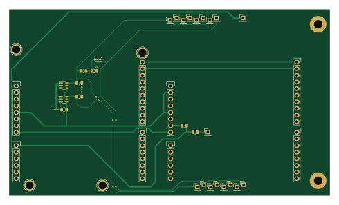
About the Ard ltc2499-test PCB
Ard ltc2499-test is an open source AVR/Arduino PCB design by IowaScaledEngineering, published on GitHub. It is a 2-layer board measuring 122.3 × 71.1 mm, with 40 components from 16 distinct parts.
Its main chip is the Arduino_1pin, from the AVR/Arduino family. Other key parts include the LT6654xxS6-1.25 and LT6654xxS6-2.5. By type, the board carries 18 test points, 8 connectors, 4 resistors, 3 capacitors, 2 ICs and 1 jumper.
It belongs with the dev boards & breakouts designs in this gallery.
From the project
Software and hardware for ISE's ARD-LTC2499 16-Channel 24-Bit ADC Data Acquisition Arduino Shield
The ARD-LTC2499 is an Arduino-compatible shield that contains a Linear Technology LTC2499 24-bit ADC coupled with an LT6654 precision voltage reference. It is capable of converting 16 single-ended channels, 8 differential channels, or any other combination. In addition to measuring voltage, the ADC can interface directly to a variety of sensors including strain gauges, thermocouples, and current shunts. The onboard EEPROM can be used to store calibration and configuration information directly on each ARD-LTC2499 board. A 6-byte EUI-48-compatible globally unique ID number is also provided. The…
Main components on the Ard ltc2499-test
Ard ltc2499-test bill of materials (BOM)
40 components, 16 distinct parts.
| Qty | Part | Footprint | Refs |
|---|---|---|---|
| 1 | LT6654xxS6-1.25 | TSOT-23-6 | U1 |
| 1 | LT6654xxS6-2.5 | TSOT-23-6 | U2 |
| 1 | Power | Socket_Strip_Arduino_1x08 | P1 |
| 1 | Analog | Socket_Strip_Arduino_1x06 | P2 |
| 1 | Digital | Socket_Strip_Arduino_1x10 | P3 |
| 1 | Digital | Socket_Strip_Arduino_1x08 | P4 |
| 4 | CONN_01X01 | Arduino_1pin | P5, P6, P7, P8 |
| 1 | SolderJumper_2_Open | SolderJumper-2_P1.3mm_Open_RoundedPad1.0x1.5mm | JP1 |
| 1 | Power | Socket_Strip_Arduino_1x08 | PX1 |
| 1 | Analog | Socket_Strip_Arduino_1x06 | PX2 |
| 1 | Digital | Socket_Strip_Arduino_1x10 | PX3 |
| 1 | Digital | Socket_Strip_Arduino_1x08 | PX4 |
| 18 | TestPoint | PinHeader_1x01_P2.54mm_Vertical | TP1, TP2, TP3, TP4, TP5, TP6, TP7, TP8 +10 |
| 2 | 1uF | C_0805_2012Metric | C1, C2 |
| 1 | 10uF | C_0805_2012Metric | C3 |
| 4 | 10k | R_0805_2012Metric | R1, R2, R3, R4 |
Ard ltc2499-test design files
The KiCad project lives in the IowaScaledEngineering/ard-ltc2499 repository on GitHub; these links point at the commit this page was built from.
Ard ltc2499-test: common questions
What microcontroller does the Ard ltc2499-test use?
The Ard ltc2499-test is built around the Arduino_1pin, from the AVR/Arduino family.
How big is the Ard ltc2499-test PCB?
The Ard ltc2499-test measures 122.3 × 71.1 mm, has 2 copper layers and is 1.6 mm thick.
How many components are on the Ard ltc2499-test?
40 components, from 16 distinct parts. The full bill of materials is listed on this page.
Where can I download the Ard ltc2499-test design files?
From the IowaScaledEngineering/ard-ltc2499 repository on GitHub, which has the KiCad layout and the schematic; the links under Design files point to each one.
Can I use the Ard ltc2499-test design in my own project?
The repository has no license, so all rights stay with IowaScaledEngineering. Use it as a reference, and ask the author before reusing the design.
Can I test firmware for the Ard ltc2499-test without the hardware?
Yes. HardLabs builds a simulation of the board from its netlist and BOM, so you can run and debug AVR/Arduino firmware against it before you order a PCB.
More boards in ard-ltc2499
Similar boards
 AVR/Arduino
Redox keyboard
mattdibi
162.2 × 126.5 mm77 parts2LMIT2.0k AVR/Arduino
ModuleV450
stuartpittaway
30 × 61.4 mm39 parts2LCC-BY-NC-4.01.1k AVR/Arduino
V4
30 × 50 mm38 parts2LCC-BY-NC-4.01.1k AVR/Arduino
Discipline
coseyfannitutti
304.9 × 122.8 mm170 parts2LCC-BY-NC-4.01.0k AVR/Arduino
Megadesk
gcormier
41.7 × 32.2 mm23 parts2LGPL-3.0818 AVR/Arduino
Easyduino Atmega Nano
Hanqaqa
43.4 × 18 mm30 parts4LCERN-OHL-P-2.0746