
Smu switch

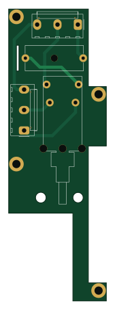
About the Smu switch PCB
Smu switch is an open source PCB design by jaromir-sukuba, published on GitHub. It is a 2-layer board measuring 38 × 113 mm, with 4 components from 3 distinct parts.
By type, the board carries 2 connectors, 1 fuse and 1 switch.
From the project
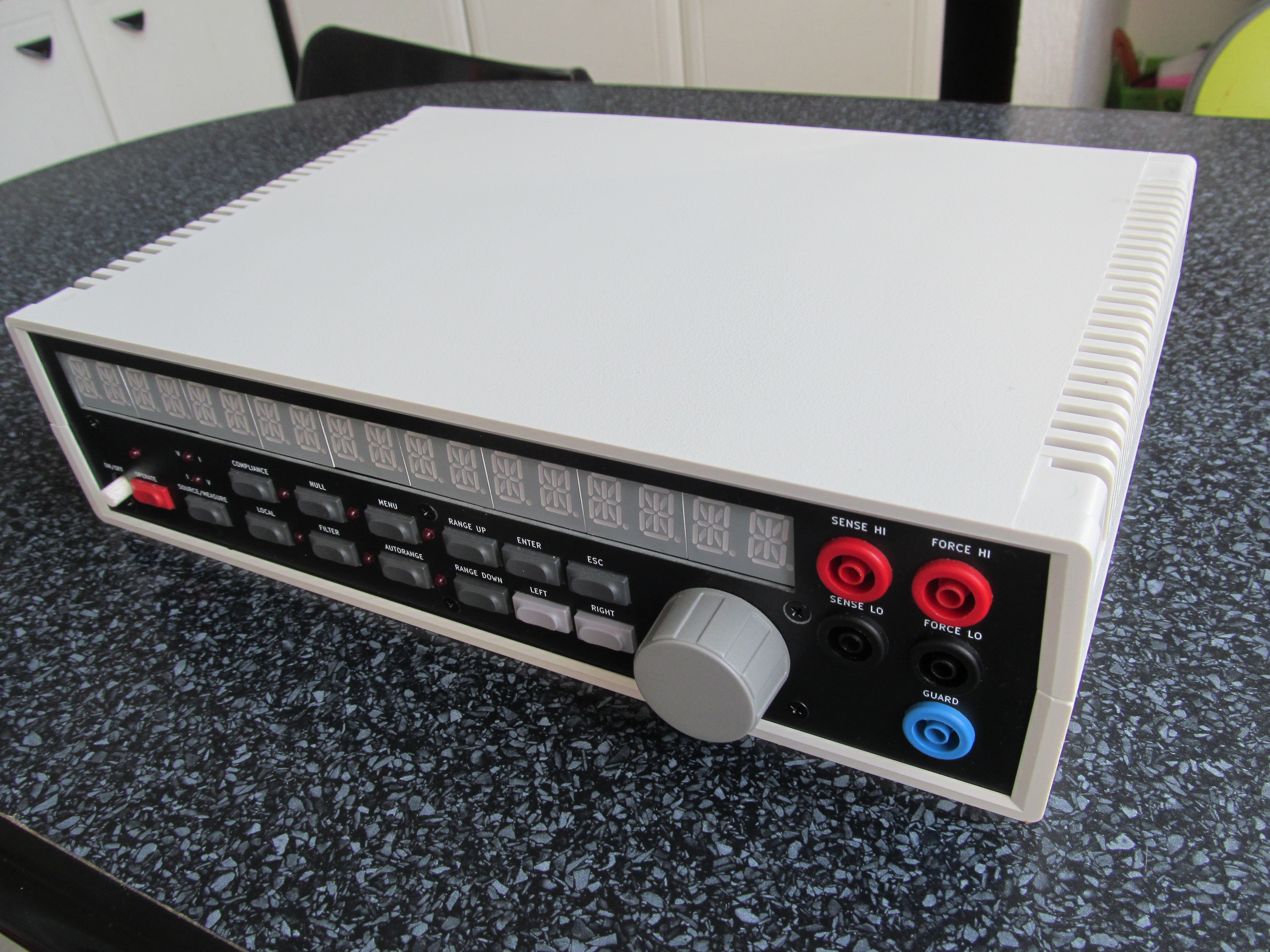
DIY source-measure unit
Parameters: + Voltage ranges 12V and 120V (bipolar) + Current ranges 1uA, 10uA, 100uA, 1mA, 10mA, 100mA (bipolar) + Minimal set voltage step - 1mV + Minimal set current step - 100pA + Voltage resolution - 100uV + Current resolution - 1pA
JSMU is designed to work as standalone device, but can be connected to computer via USB, and controlled via simple commands in SCPI form, similar to Keithley 2xxx series SMUs.
Smu switch bill of materials (BOM)
4 components, 3 distinct parts.
| Qty | Part | Footprint | Refs |
|---|---|---|---|
| 2 | Conn_01x05_Male | Molex_KK-396_A-41791-0005_1x05_P3.96mm_Vertical | J1, J2 |
| 1 | Fuse | Fuseholder_Cylinder-5x20mm_Schurter_0031_8201_Horizontal_Open | F1 |
| 1 | SW_DPST | NE18-2P | SW1 |
Smu switch design files
The KiCad project lives in the jaromir-sukuba/J-SMU repository on GitHub; these links point at the commit this page was built from.
Smu switch: common questions
How big is the Smu switch PCB?
The Smu switch measures 38 × 113 mm, has 2 copper layers and is 1.6 mm thick.
How many components are on the Smu switch?
4 components, from 3 distinct parts. The full bill of materials is listed on this page.
Where can I download the Smu switch design files?
From the jaromir-sukuba/J-SMU repository on GitHub, which has the KiCad layout; the links under Design files point to each one.
Can I use the Smu switch design in my own project?
The repository has no license, so all rights stay with jaromir-sukuba. Use it as a reference, and ask the author before reusing the design.
More boards in J-SMU
 AVR/Arduino
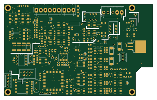
Smu main 1
130 × 80 mm206 parts2LNo license188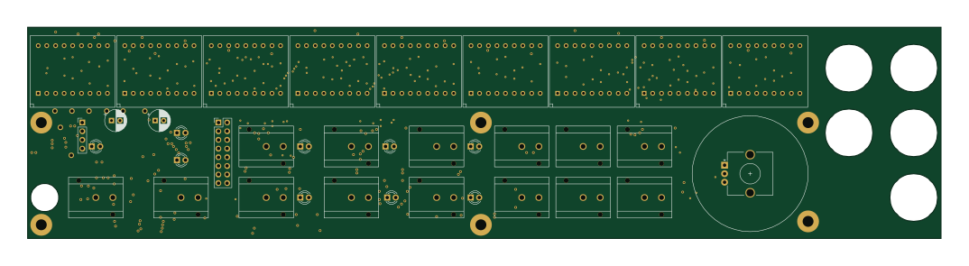
Smu front 1
268 × 62 mm83 parts2LNo license188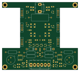
Smu amp 1
84 × 75 mm69 parts2LNo license188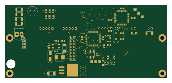 PIC
PICSmu subfront 1
137 × 62 mm56 parts2LNo license188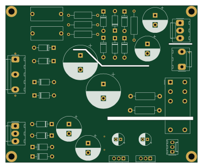
Smu pwr 1
100 × 82 mm38 parts2LNo license188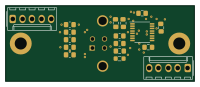
Smu back usb
50 × 20 mm18 parts2LNo license188