
SDBox v3

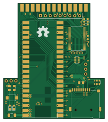
About the SDBox v3 PCB
SDBox v3 is an open source PCB design by jbilander, published on GitHub under the GPL-3.0 license. It is a 2-layer board measuring 52.5 × 60 mm, with 19 components from 17 distinct parts.
Other key parts include the Rapberry_Pi_Pico_2W and SN74CBT16210. By type, the board carries 7 resistors, 3 connectors, 3 diodes, 3 capacitors, 2 ICs and 1 battery holder.
It belongs with the retro computing designs in this gallery.
From the project
A parallel to Pico 2 W and sd-card project for the Amiga
Firmware for this project with support for a blinking activity LED can be built from source here: https://github.com/jbilander/amiga-par-to-spi-adapter/tree/master/rp2350
BOM Rev. 3C --------- same as 3B but with these changes: Reference | Name/Value | Package | Notes -|-|-|-| BT1 | Push button | SunromTactileSwitch3x4x2mmSMD2-Pin | Aliexpress D1-D2 (Optional) | SMD LED | 0603 | Aliexpress R1 (Optional) | 1k Ω | 0805 | (Mandatory if D1 populated) Series resistor for D1 LED, adjust R-value to your type of LED and preferred brightness R2 (Optional) | 1k Ω | 0805 | (Mandatory if D2 populated)…
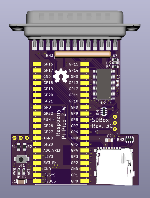
Main components on the SDBox v3
SDBox v3 bill of materials (BOM)
19 components, 17 distinct parts.
| Qty | Part | Footprint | Refs |
|---|---|---|---|
| 1 | Rapberry_Pi_Pico_2W | RPi_Pico_SMD | U1 |
| 1 | SN74CBT16210 | TSSOP-48_6.1x12.5mm_P0.5mm | U2 |
| 1 | DB25_Male | DSUB-25_Male_EdgeMount_P2.77mm | J1 |
| 1 | Micro_SD_Card_Socket | GCT-MEM2055-00-190-01-A | J2 |
| 1 | Conn_01x05 | UART_PinHeader_SMD_pads_2.54mm_pitch | J3 |
| 1 | SW_Push | Sunrom_Tactile_Switch_3x4x2mm_SMD_2-Pin | BT1 |
| 1 | Power LED indicator | D_0603_1608Metric_Pad1.05x0.95mm_HandSolder | D1 |
| 1 | Activity LED indicator | D_0603_1608Metric_Pad1.05x0.95mm_HandSolder | D2 |
| 1 | MMDL6050T1G | D_0603_1608Metric_Pad1.05x0.95mm_HandSolder | D3 |
| 1 | 10uF | C_1206_3216Metric_Pad1.33x1.80mm_HandSolder | C1 |
| 1 | 0.1uF | C_0805_2012Metric_Pad1.15x1.40mm_HandSolder | C2 |
| 1 | 0.1uF | C_0603_1608Metric_Pad1.08x0.95mm_HandSolder | C3 |
| 2 | 1k | R_0805_2012Metric_Pad1.15x1.40mm_HandSolder | R1, R2 |
| 1 | 10k | R_0603_1608Metric_Pad0.98x0.95mm_HandSolder | R3 |
| 1 | 2.9k | R_0603_1608Metric_Pad0.98x0.95mm_HandSolder | R4 |
| 2 | 10k_R_Pack04 | RESCAF80P320X160X60-8N | RN1, RN2 |
| 1 | 10k | R_Array_SIP9 | RN3 |
SDBox v3 design files
The KiCad project lives in the jbilander/SDBox-v3 repository on GitHub; these links point at the commit this page was built from.
- LayoutKiCad/SDBox.kicad_pcb
SDBox v3: common questions
How big is the SDBox v3 PCB?
The SDBox v3 measures 52.5 × 60 mm, has 2 copper layers and is 1.6 mm thick.
How many components are on the SDBox v3?
19 components, from 17 distinct parts. The full bill of materials is listed on this page.
Where can I download the SDBox v3 design files?
From the jbilander/SDBox-v3 repository on GitHub, which has the KiCad layout; the links under Design files point to each one.
Can I use the SDBox v3 design in my own project?
Yes, under the terms of its GPL-3.0 license, which jbilander chose for the repository.
Similar boards
Expansion Card Retrofit
FrameworkComputer
24 × 27.3 mm5 parts2LCC-BY-4.01.1k
Rgb to hdmi
hoglet67
77 × 97 mm67 parts2LGPL-3.01.0k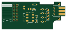
Buffer
53.9 × 23.2 mm13 parts2LGPL-3.01.0k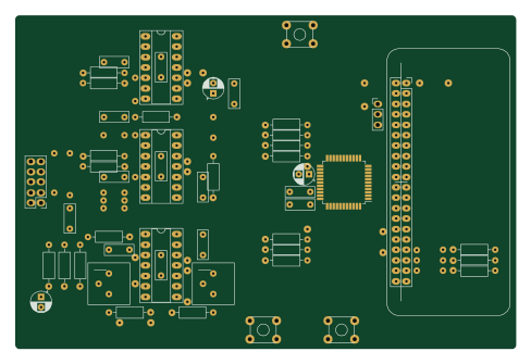
X1
121.9 × 81.3 mm51 parts2LGPL-3.01.0k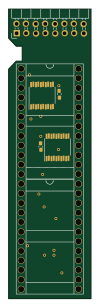
Amiga External
21.9 × 76.7 mm6 parts2LGPL-3.01.0k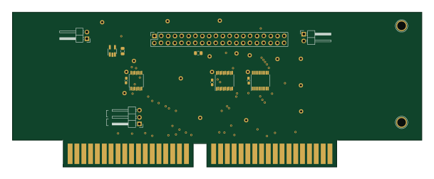
Videoslotadapter
152 × 57.6 mm13 parts2LGPL-3.01.0k