Mic test

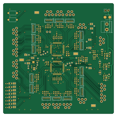
About the Mic test PCB
Mic test is an open source PCB design by jbrryhooves, published on GitHub. It is a 4-layer board measuring 100 × 100 mm, with 307 components from 28 distinct parts.
Other key parts include the LMK1C1102DQFR, AD7768BSTZ, MAX6070BAUT33+T, NUCLEO144-H743ZI and LP5912-5.0DRVR. By type, the board carries 99 capacitors, 86 test points, 78 resistors, 18 connectors, 11 diodes and 9 ICs.
Main components on the Mic test
Mic test bill of materials (BOM)
307 components, 28 distinct parts — part numbers from the project's BOM.
| Qty | Part | Footprint | Refs |
|---|---|---|---|
| 1 | LMK1C1102DQFR LMK1C1102 Texas Instruments | WSON-8-1EP_2x2mm_P0.5mm_EP0.9x1.6mm | U1 |
| 2 | AD7768BSTZ Analog Devices Inc. | LQFP-64_10x10mm_P0.5mm | U2, U6 |
| 1 | MAX6070BAUT33+T Analog Devices Inc./Maxim Integrated | SOT-23-6 | U3 |
| 1 | NUCLEO144-H743ZI | ST_Morpho_Connector_144_STLink_SMD_Headers_BottomMount | U5 |
| 1 | LP5912-5.0DRVR LP5912-5.0DRV Texas Instruments | WSON-6-1EP_2x2mm_P0.65mm_EP1x1.6mm_ThermalVias | U22 |
| 2 | LP5912-3.3DRVR LP5912-3.3DRV Texas Instruments | WSON-6-1EP_2x2mm_P0.65mm_EP1x1.6mm_ThermalVias | U23, U24 |
| 1 | SN74LVC126ARGYR Texas Instruments | IC_SN74AUC08RGYRG4 | U34 |
| 1 | KC3225Z32.7680C1KX00 KYOCERA AVX | Oscillator_SMD_SeikoEpson_SG210-4Pin_2.5x2.0mm | X1 |
| 1 | Conn_01x03 | PinHeader_1x02_P2.54mm_Vertical | J3 |
| 1 | 1715022 Conn_01x03 Phoenix Contact | TerminalBlock_Phoenix_MKDS-1,5-2_1x02_P5.00mm_Horizontal | J4 |
| 16 | 0530470510 Conn_01x04 Molex | Molex_PicoBlade_53047-0510_1x05_P1.25mm_Vertical | J7, J8, J9, J11, J13, J15, J17, J19 +8 |
| 3 | SolderJumper_3_Open | SolderJumper-3_P1.3mm_Open_RoundedPad1.0x1.5mm_NumberLabels | JP1, JP2, JP18 |
| 2 | RS-282G05A3-SM RT SW_Push C&K | SW_SPST_CK_RS282G05A3 | SW1, SW2 |
| 2 | Hole_1.5mm | TestPoint_THTPad_D1.5mm_Drill0.7mm | TP4, TP36 |
| 80 | Hole_1.5mm | TestPoint_THTPad_D2.0mm_Drill1.0mm | TP38, TP39, TP40, TP41, TP42, TP43, TP44, TP45 +72 |
| 1 | 5019 Keystone Electronics | TestPoint_Keystone_5019_Minature | TP118 |
| 3 | 5019 Hole_1.5mm Keystone Electronics | TestPoint_Keystone_5019_Minature | TP119, TP120, TP121 |
| 10 | SML-LX0805SRC-TR LED_Small_Filled Lumex Opto/Components Inc. | LED_0805_2012Metric | D1, D2, D3, D4, D5, D6, D7, D8 +2 |
| 1 | SMBJ5340BE3/TR13 Microchip Technology | D_SMB | D11 |
| 22 | CC0603KRX7R7BB105 1uF YAGEO | C_0603_1608Metric | C1, C3, C5, C7, C9, C12, C15, C19 +14 |
Show 8 more
| Qty | Part | Footprint | Refs |
|---|---|---|---|
| 27 | CC0603KRX7R7BB104 0.1uF YAGEO | C_0603_1608Metric | C2, C4, C6, C8, C10, C11, C13, C14 +19 |
| 2 | CL21B106KOQNNNE 10uF Samsung Electro-Mechanics | C_0805_2012Metric | C16, C77 |
| 48 | C0603C103M4RAC7867 10nF KEMET | C_0603_1608Metric | C18, C20, C26, C27, C29, C30, C33, C35 +40 |
| 2 | ERJ-3EKF49R9V 49.9R Panasonic Electronic Components | R_0603_1608Metric | R1, R40 |
| 27 | RMCF0603ZT0R00 0R Stackpole Electronics Inc | R_0603_1608Metric | R2, R3, R8, R14, R20, R26, R27, R28 +19 |
| 10 | RC0603JR-07470RL 470R YAGEO | R_0603_1608Metric | R4, R33, R135, R136, R137, R138, R139, R140 +2 |
| 32 | CRCW060333R0FKEAC 33R Vishay Dale | R_0603_1608Metric | R5, R6, R7, R9, R12, R15, R18, R21 +24 |
| 7 | RC0603FR-07100KL 100k YAGEO | R_0603_1608Metric | R10, R11, R13, R29, R31, R34, R36 |
Mic test design files
The KiCad project lives in the jbrryhooves/sound-compass repository on GitHub; these links point at the commit this page was built from.
Mic test: common questions
How big is the Mic test PCB?
The Mic test measures 100 × 100 mm, has 4 copper layers and is 1.6 mm thick.
How many components are on the Mic test?
307 components, from 28 distinct parts, with part numbers taken from the project's own BOM. The full bill of materials is listed on this page.
Where can I download the Mic test design files?
From the jbrryhooves/sound-compass repository on GitHub, which has the KiCad layout, the schematic and the BOM; the links under Design files point to each one.
Can I use the Mic test design in my own project?
The repository has no license, so all rights stay with jbrryhooves. Use it as a reference, and ask the author before reusing the design.