
Pcb analog feedback loop

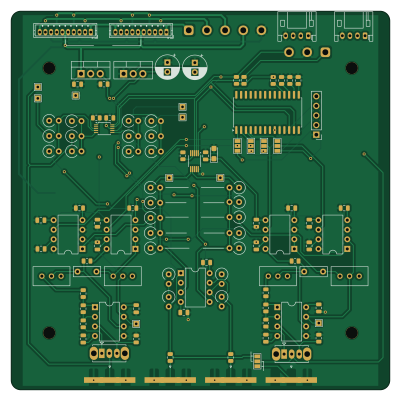
About the Pcb analog feedback loop
Pcb analog feedback loop is an open source PCB design by jc-roth, published on GitHub. It is a 4-layer board measuring 100 × 100 mm, with 109 components from 30 distinct parts.
Other key parts include the AD823, ADG419BN, MCP23017_SO, C37593 and C108207. By type, the board carries 46 resistors, 27 capacitors, 12 ICs, 9 connectors, 9 test points and 2 switches.
From the project
KiCAD project for an analog feedback loop circuit
For our use case, the advantage this circuit provides over a fully analog feedback loop is that it is straightforward to implement autolocking logic, unlock detection, etc. Since the actual feedback loop is fully analog, it can retain a high closed loop bandwidth. While a similar result could likely be achieved with an FPGA, this approach is more accessible to those unfamiliar with FPGA programming. Dependning on the FPGA used, it might also achieve a higher closed loop bandwidth.
Main components on the Pcb analog feedback loop
Pcb analog feedback loop bill of materials (BOM)
109 components, 30 distinct parts — part numbers from the project's BOM.
| Qty | Part | Footprint | Refs |
|---|---|---|---|
| 3 | AD823 | DIP-8_W7.62mm | U1, U4, U5 |
| 4 | ADG419BN | DIP-8_W7.62mm | U2, U3, U6, U7 |
| 1 | MCP23017_SO | SOIC-28W_7.5x17.9mm_P1.27mm | U8 |
| 1 | C37593 ADS1115IDGS | TSSOP-10_3x3mm_P0.5mm | U9 |
| 1 | C108207 MCP4728 | MSOP-10_3x3mm_P0.5mm | U10 |
| 1 | LM7809_TO220 | TO-220-3_Vertical | U11 |
| 1 | LM7909_TO220 | TO-220-3_Vertical | U12 |
| 1 | primary error in | SMA_Amphenol_132289_EdgeMount | J1 |
| 1 | primary control out | SMA_Amphenol_132289_EdgeMount | J3 |
| 1 | secondary error in | SMA_Amphenol_132289_EdgeMount | J4 |
| 1 | secondary control out | SMA_Amphenol_132289_EdgeMount | J6 |
| 1 | CONN_01X05 Conn_01x05 | PinHeader_1x05_P2.54mm_Vertical | J7 |
| 2 | CONN_01X10_PIN Conn_01x10_Pin | JST_ZH_B10B-ZR_1x10_P1.50mm_Vertical | J11, J12 |
| 2 | CONN_01X04_PIN Conn_01x04_Pin | JST_PH_S4B-PH-K_1x04_P2.00mm_Horizontal | J15, J16 |
| 2 | 500K 500k | Potentiometer_Bourns_3296W_Vertical | RV1, RV3 |
| 2 | 20K 20k | Potentiometer_Bourns_3296W_Vertical | RV2, RV4 |
| 1 | primary polarity | SW_Slide_SPDT_Straight_CK_OS102011MS2Q | SW1 |
| 1 | secondary polarity | SW_Slide_SPDT_Straight_CK_OS102011MS2Q | SW2 |
| 9 | TestPoint | TestPoint_THTPad_1.5x1.5mm_Drill0.7mm | TP1, TP2, TP3, TP4, TP5, TP6, TP7, TP8 +1 |
| 2 | C | C_Disc_D7.0mm_W2.5mm_P5.00mm | C1, C2 |
Show 10 more
| Qty | Part | Footprint | Refs |
|---|---|---|---|
| 6 | C1710 10n | C_0805_2012Metric | C3, C4, C5, C6, C7, C8 |
| 15 | C28233 100n | C_0805_2012Metric | C9, C10, C11, C12, C13, C14, C15, C16 +7 |
| 1 | C1740 330n | C_0805_2012Metric | C23 |
| 1 | C7171 10u, tantalum | CP_EIA-3216-18_Kemet-A | C24 |
| 1 | 2.2U 2.2u | CP_Radial_D6.3mm_P2.50mm | C26 |
| 1 | 1u | CP_Radial_D6.3mm_P2.50mm | C27 |
| 13 | C17414 10k | R_0805_2012Metric | R1, R2, R3, R12, R13, R14, R23, R24 +5 |
| 6 | C17408 100 | R_0805_2012Metric | R4, R15, R25, R26, R44, R45 |
| 26 | R | R_Axial_DIN0309_L9.0mm_D3.2mm_P2.54mm_Vertical | R5, R6, R7, R8, R9, R10, R11, R16 +18 |
| 1 | C17673 4.7k | R_0805_2012Metric | R49 |
Pcb analog feedback loop design files
The KiCad project lives in the jc-roth/pcb_analog_feedback_loop repository on GitHub; these links point at the commit this page was built from.
- Layoutfeedback_loop.kicad_pcb
- Schematicfeedback_loop.kicad_sch
- BOMproduction/BOM.csv
Pcb analog feedback loop: common questions
How big is the Pcb analog feedback loop?
The Pcb analog feedback loop measures 100 × 100 mm, has 4 copper layers and is 1.6 mm thick.
How many components are on the Pcb analog feedback loop?
109 components, from 30 distinct parts, with part numbers taken from the project's own BOM. The full bill of materials is listed on this page.
Where can I download the Pcb analog feedback loop design files?
From the jc-roth/pcb_analog_feedback_loop repository on GitHub, which has the KiCad layout, the schematic and the BOM; the links under Design files point to each one.
Can I use the Pcb analog feedback loop design in my own project?
The repository has no license, so all rights stay with jc-roth. Use it as a reference, and ask the author before reusing the design.