
BackplanePCB solder.kicad pcb LEFT

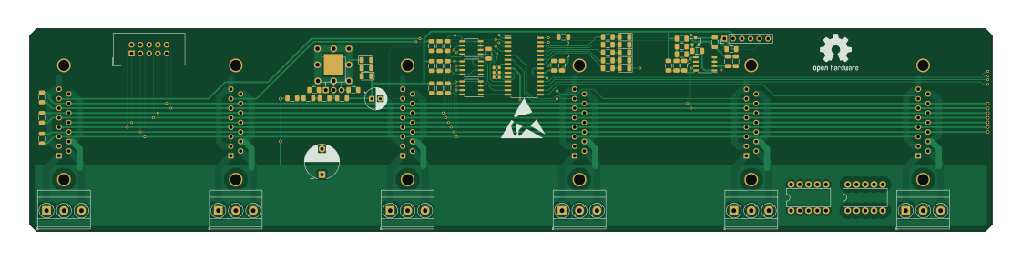
About the BackplanePCB solder.kicad pcb LEFT
BackplanePCB solder.kicad pcb LEFT is an open source PIC PCB design by jeremysiebers, published on GitHub. It is a 2-layer board measuring 280 × 59 mm, with 68 components from 36 distinct parts.
Its main chip is the PIC16F15345-I_GZ-MCU_MICROCHIP_PIC16_UQFN_20_4X4, from the PIC family. Other key parts include the MCP73871-2AA_VQFN_20_4X4, MCP1725-ADJE_MC_DFN-8-REGULATOR_LINEAR, KA78M05_TO252, ST485EBDR and PIC16F18854-SO. By type, the board carries 26 resistors, 18 capacitors, 10 connectors, 7 diodes, 6 ICs and 1 transistor.
From the project
Siebwalde project
This project is dedicated for the ModelTrain Yard of Siebwalde: - https://www.youtube.com/c/SiebersOrg - http://www.siebers.org/index.html - https://www.youtube.com/channel/UCRJYaY8l7wVBrel3Bn0nD2Q/videos?view_as=subscriber
- Siebwalde_Application --> C# main App to control all
- FiddleYard --> Embedded ethernet uController, controlling the FiddleYard PIC18F97j60
Main components on the BackplanePCB solder.kicad pcb LEFT
BackplanePCB solder.kicad pcb LEFT bill of materials (BOM)
68 components, 36 distinct parts — part numbers from the project's BOM.
| Qty | Part | Footprint | Refs |
|---|---|---|---|
| 1 | PIC16F15345-I_GZ-MCU_MICROCHIP_PIC16_UQFN_20_4X4 ST485EBDR | SOIC-8_3.9x4.9mm_P1.27mm | U1 |
| 1 | MCP73871-2AA_VQFN_20_4X4 ST485EBDR | SOIC-8_3.9x4.9mm_P1.27mm | U2 |
| 1 | MCP1725-ADJE_MC_DFN-8-REGULATOR_LINEAR ST485EBDR | SOIC-8_3.9x4.9mm_P1.27mm | U3 |
| 1 | KA78M05_TO252 | TO-251-3-1EP_Horizontal_TabDown | U4 |
| 1 | ST485EBDR | SOIC-8_3.9x4.9mm_P1.27mm | U5 |
| 1 | PIC16F18854-SO | SOIC-28W_7.5x17.9mm_P1.27mm | U6 |
| 1 | Q_NMOS_GSD | SOT-23 | Q1 |
| 1 | Conn_02x05_Odd_Even | IDC-Header_2x05_P2.54mm_Vertical | J1 |
| 1 | PowerBug+15V | DIP-10_W7.62mm | J3 |
| 1 | PowerBug_GND | DIP-10_W7.62mm | J4 |
| 6 | Conn_01x03 | TerminalBlock_Phoenix_MKDS-3-3-5.08_1x03_P5.08mm_Horizontal | J5, J6, J7, J10, J11, J12 |
| 1 | Conn_01x06 | PinHeader_1x06_P2.54mm_Vertical | J25 |
| 1 | SMAJ5.0A/AC D_Zener | D_1206_3216Metric | D1 |
| 1 | LED | D_1206_3216Metric | D2 |
| 3 | LED GR | D_1206_3216Metric | D3, D6, D7 |
| 1 | LED YE | D_1206_3216Metric | D4 |
| 1 | LED RD | D_1206_3216Metric | D5 |
| 1 | 0.1UF 470u | CP_Radial_D10.0mm_P7.50mm | C2 |
| 4 | 4.7UF C | C_1206_3216Metric | C3, C5, C6, C7 |
| 1 | 10UF C | C_1206_3216Metric | C4 |
Show 16 more
| Qty | Part | Footprint | Refs |
|---|---|---|---|
| 11 | C | C_1206_3216Metric | C8, C9, C10, C11, C12, C13, C14, C15 +3 |
| 1 | CP | CP_Radial_D6.3mm_P2.50mm | C16 |
| 3 | 4.7K 120E | R_1206_3216Metric | R1, R2, R3 |
| 1 | 18K R | R_1206_3216Metric | R4 |
| 2 | 200 R | R_1206_3216Metric | R5, R6 |
| 1 | 220K R | R_1206_3216Metric | R7 |
| 1 | 10K R | R_1206_3216Metric | R8 |
| 1 | 4.7K R | R_1206_3216Metric | R9 |
| 1 | 47K R | R_1206_3216Metric | R10 |
| 1 | 22K R | R_1206_3216Metric | R11 |
| 2 | 470 R | R_1206_3216Metric | R12, R13 |
| 1 | 470 R | R_0603_1608Metric | R14 |
| 1 | 4.7K R | R_0603_1608Metric | R15 |
| 1 | 150 R | R_0603_1608Metric | R16 |
| 9 | 150 R | R_1206_3216Metric | R17, R18, R19, R20, R21, R22, R23, R24 +1 |
| 1 | R | R_1206_3216Metric | R26 |
BackplanePCB solder.kicad pcb LEFT design files
The KiCad project lives in the jeremysiebers/Siebwalde repository on GitHub; these links point at the commit this page was built from.
BackplanePCB solder.kicad pcb LEFT: common questions
What microcontroller does the BackplanePCB solder.kicad pcb LEFT use?
The BackplanePCB solder.kicad pcb LEFT is built around the PIC16F15345-I_GZ-MCU_MICROCHIP_PIC16_UQFN_20_4X4, from the PIC family.
How big is the BackplanePCB solder.kicad pcb LEFT?
The BackplanePCB solder.kicad pcb LEFT measures 280 × 59 mm, has 2 copper layers and is 1.6 mm thick.
How many components are on the BackplanePCB solder.kicad pcb LEFT?
68 components, from 36 distinct parts, with part numbers taken from the project's own BOM. The full bill of materials is listed on this page.
Where can I download the BackplanePCB solder.kicad pcb LEFT design files?
From the jeremysiebers/Siebwalde repository on GitHub, which has the KiCad layout and the BOM; the links under Design files point to each one.
Can I use the BackplanePCB solder.kicad pcb LEFT design in my own project?
The repository has no license, so all rights stay with jeremysiebers. Use it as a reference, and ask the author before reusing the design.
Can I test firmware for the BackplanePCB solder.kicad pcb LEFT without the hardware?
Yes. HardLabs builds a simulation of the board from its netlist and BOM, so you can run and debug PIC firmware against it before you order a PCB.
More boards in Siebwalde
 PIC
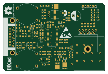
PICTrackAmplifier
105 × 70 mm117 parts2LNo license0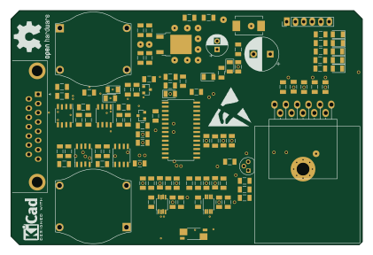 PIC
PICTrackAmplifier before DSUB flip
105 × 70 mm103 parts2LNo license0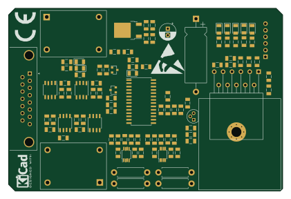 PIC
PICTrackAmplifier LMD18200 up right
105 × 70 mm97 parts2LNo license0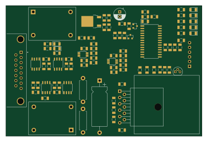 PIC
PICTrackAmplifier LMD18200 down right
105 × 70 mm94 parts2LNo license0 PIC
PICBackplanePCB solder
470 × 59 mm88 parts2LNo license0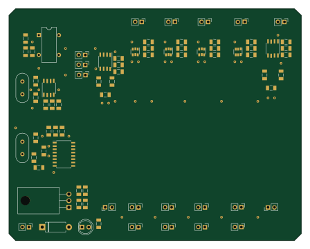 PIC
PICClockDistrTest
111.8 × 88.9 mm77 parts2LNo license0 PIC
PICBackplanePCB solder.kicad pcb RIGHT
470 × 59 mm74 parts2LNo license0 PIC
PICTrackModBusMaster piggyback
40 × 77 mm65 parts2LNo license0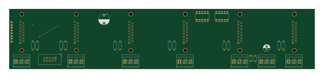
BackplanePCB solder Left
280 × 55 mm30 parts2LNo license0
BackplanePCB - 550mm
550 × 35 mm29 parts2LNo license0
Backplane
460 × 35 mm28 parts2LNo license0
Similar boards
 PIC
PICPslab hardware
fossasia
99 × 53.3 mm187 parts4LApache-2.01.7k PIC
PICMicro 8088
skiselev
152.4 × 101.6 mm71 partsGPL-3.0414 PIC
PICGB-CARTPP-DIY
Gekkio
100 × 100 mm22 parts2LCC-BY-4.0376 PIC
PICGB-MBCTEST
51.4 × 61 mm32 parts2LCC-BY-4.0376 PIC
PICGB-BENCH-G1
100 × 100 mm98 parts4LCC-BY-4.0376 PIC
PICGB-LIVE32
51.4 × 61 mm46 parts4LCC-BY-4.0376