
19 open source boards using the ST485EBDR
Real designs built with the ST485EBDR, from public GitHub projects: a quick way to see how others power, decouple and connect it. Each board comes with its KiCad files, full parts list and a render — and you can simulate its firmware on HardLabs.
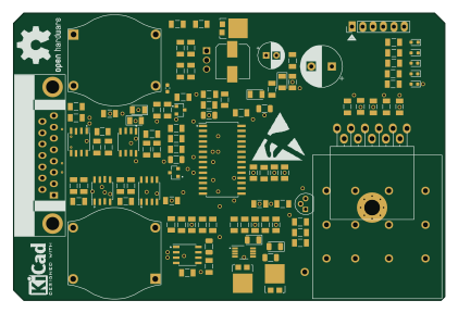 PIC
TrackAmplifier
jeremysiebers
105 × 70 mm117 parts2LNo license0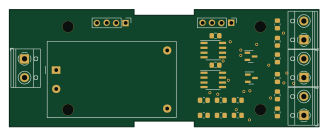
Modbus RTU mirror base board
galopago
82 × 31 mm25 parts2LCC-BY-4.07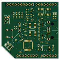 AVR/Arduino
Shield
ksmonkey123
52.7 × 53.3 mm57 parts2LMIT1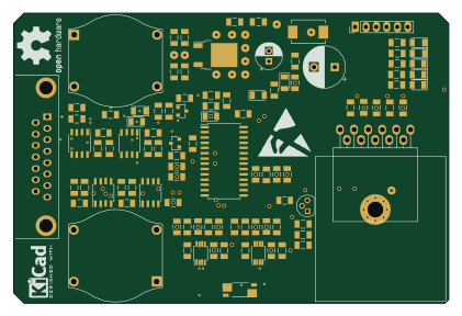 PIC
TrackAmplifier before DSUB flip
105 × 70 mm103 parts2LNo license0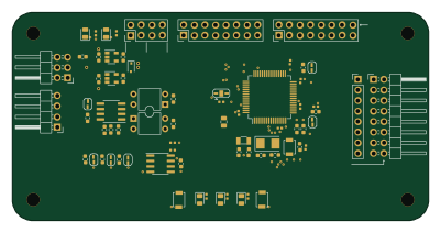 STM32
Stm32f373rct6 evaluation board
koson
100 × 50 mm65 parts2LNo license0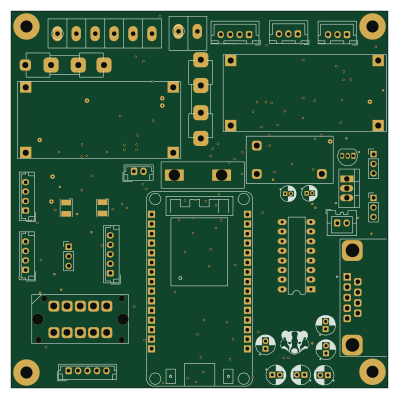 ESP32
ESP32 master
kwiecinski
99.5 × 99.5 mm153 parts2LMIT3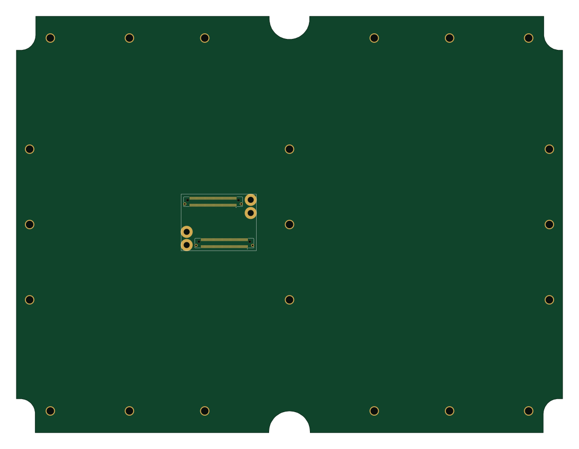
Hub module
tmolteno
290 × 221 mm64 parts2LGPL-3.01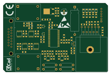 PIC
TrackAmplifier LMD18200 up right
105 × 70 mm97 parts2LNo license0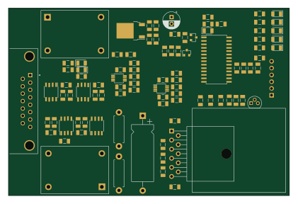 PIC
TrackAmplifier LMD18200 down right
105 × 70 mm94 parts2LNo license0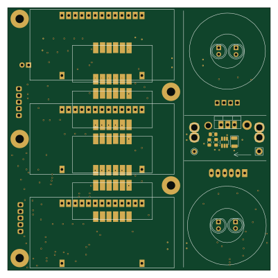
DC line module+Meter probe
100 × 100 mm98 parts2LMIT3 PIC
BackplanePCB solder
470 × 59 mm88 parts2LNo license0 AVR/Arduino
RotationEncoder
nunosousa
50 × 25 mm47 parts4LMIT0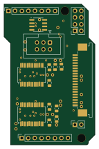
DataShield
34.6 × 53.3 mm31 parts4LMIT0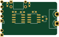
Isolated rs485 transceiver
29 × 17.8 mm12 parts2LNo license0 PIC
BackplanePCB solder.kicad pcb RIGHT
470 × 59 mm74 parts2LNo license0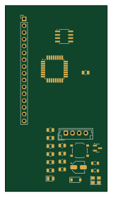 AVR/Arduino
DataDisplay
38.1 × 69.3 mm30 parts2LMIT0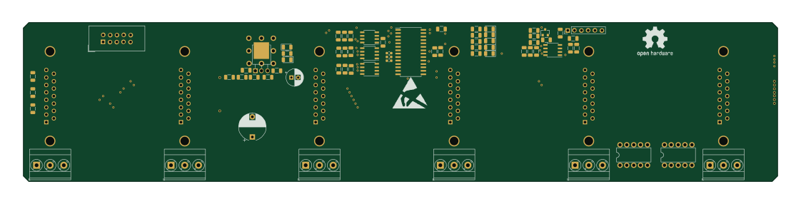 PIC
BackplanePCB solder.kicad pcb LEFT
280 × 59 mm68 parts2LNo license0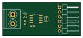
Rs485 transceiver
42 × 18 mm5 parts2LNo license0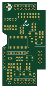 PIC
TrackModBusMaster piggyback
40 × 77 mm65 parts2LNo license0
How designs wire the ST485EBDR
Read from the KiCad layouts of 7 open source designs, one per repository: what each pin of the ST485EBDR connects to, and the resistors, capacitors and other passives placed on it.
- The A pin has a series resistor on 5 of 7 designs, most often 0 Ω (then 120 Ω).
- The B pin has a series resistor on 5 of 7 designs, most often 120 Ω (then 0 Ω).
- The VCC pin has a decoupling capacitor on 3 of 7 designs, most often 100 nF (then 4.7 µF).
| Pin | Connected to | Parts on the pin |
|---|---|---|
| GNDpin 5 | Connected to: GND 86% | — |
| Apin 6 | Connected to: A connector 86% |
|
| Bpin 7 | Connected to: A connector 86% |
|
| VCCpin 8 | Connected to: 5V 71% |
|
4 more pins vary from design to design. Connections count pins, parts count designs; values in brackets are how many parts had that value. Designs read include Modbus RTU mirror base board by galopago, DC line module+Meter probe by kwiecinski, Shield by ksmonkey123 and Hub module by tmolteno.
The ST485EBDR in open source designs
The gallery holds 19 open source boards using the ST485EBDR from 7 GitHub repositories; a typical one measures about 100 × 59 mm and carries around 65 components.
89% are two-layer designs, the rest use four layers or more, and 42% carry an open source license.
The most starred is Modbus RTU mirror base board by galopago.
Parts used alongside the ST485EBDR
Microcontrollers on boards using the ST485EBDR
What boards using the ST485EBDR are built for
ST485EBDR: common questions
Where can I find a ST485EBDR reference design?
Each of the 19 boards on this page is a real design using the ST485EBDR. Open one to see how it is wired up, with the full BOM, a render of the layout and links to its KiCad files.
What resistor goes on the ST485EBDR A pin?
The A pin has a series resistor on 5 of 7 designs, most often 0 Ω (then 120 Ω). Counted from the KiCad layouts of 7 open source designs using the ST485EBDR.
What resistor goes on the ST485EBDR B pin?
The B pin has a series resistor on 5 of 7 designs, most often 120 Ω (then 0 Ω). Counted from the KiCad layouts of 7 open source designs using the ST485EBDR.
What decoupling capacitors do designs use on the ST485EBDR VCC pin?
The VCC pin has a decoupling capacitor on 3 of 7 designs, most often 100 nF (then 4.7 µF). Counted from the KiCad layouts of 7 open source designs using the ST485EBDR.
Which microcontrollers do boards using the ST485EBDR use?
Most are built on PIC (8), AVR/Arduino (3), ESP32 (1) and STM32 (1).
How big is a typical board using the ST485EBDR?
The median is 100 × 59 mm, and 89% are two-layer designs.
What is the most popular open source board using the ST485EBDR?
By GitHub stars, Modbus RTU mirror base board by galopago, with 7 stars.
Can I simulate one of these boards using the ST485EBDR before building it?
Yes. HardLabs turns a board's netlist and BOM into a working simulation, so you can boot and test firmware against it with no hardware on your desk.