
RoomSensor 001 LCD

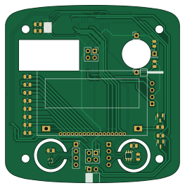
About the RoomSensor 001 LCD PCB
RoomSensor 001 LCD is an open source PCB design by jirihusak, published on GitHub under the GPL-3.0 license. It is a 2-layer board measuring 65.5 × 66.5 mm, with 33 components from 16 distinct parts.
Other key parts include the NHD-C12832A1Z-NSW-BBW-3V3, SGP40, SHT41-AD1F-R2 and MP34DT05-A. By type, the board carries 14 capacitors, 9 connectors, 4 ICs, 3 resistors, 2 transistors and 1 diode.
It belongs with the iot & wireless, sensors and displays & leds designs in this gallery.
From the project
Open source system for smart home
Majordomus is a modular automation system built on open standards. It fills the gap between closed, expensive commercial solutions and unreliable consumer-grade components — designed to be repairable, expandable, and to last for decades.
- 🧩 Modular hardware — base unit + interchangeable modules ( I/O, sensors) - 🔌 Standardized interface — RS-485 / ModBus HW interface, MQTT SW interface - 🔓 Vendor lock-in free — open hardware, open software, your choice - 🧠 Node-RED inside — visual programming for automation flows - 🧠 Home Assistant interface — MQTT integration for popular platform - 📡…
Main components on the RoomSensor 001 LCD
RoomSensor 001 LCD bill of materials (BOM)
33 components, 16 distinct parts.
| Qty | Part | Footprint | Refs |
|---|---|---|---|
| 1 | NHD-C12832A1Z-NSW-BBW-3V3 | NHD-C12832A1Z | U1 |
| 1 | SGP40 | SGP40 | U3 |
| 1 | SHT41-AD1F-R2 | Sensirion_DFN-4_1.5x1.5mm_P0.8mm_SHT4x_NoCentralPad | U4 |
| 1 | MP34DT05-A | MIC-PACK | U5 |
| 2 | MMBF170 | SOT-23 | Q1, Q2 |
| 1 | 68611614422 | WURTH_68611614422 | J1 |
| 2 | Conn_02x02_Odd_Even | PinSocket_2x02_P2.54mm_Vertical | J2, J3 |
| 3 | Conn_01x04 | PinSocket_1x04_P2.54mm_Vertical | J4, J5, J6 |
| 1 | Conn_01x01 | PinHeader_1x01_P2.54mm_Horizontal | J7 |
| 2 | Conn_01x01 | PinHeader_1x01_P2.54mm_Vertical | J8, J9 |
| 1 | LED LL-234WC2Q-W5-3P | PinSocket_1x02_P2.54mm_Horizontal | D1 |
| 5 | 100nF | C_0805_2012Metric | C1, C2, C3, C4, C5 |
| 9 | 1uF | C_0805_2012Metric | C6, C7, C8, C9, C10, C11, C12, C13 +1 |
| 1 | 1k5 | R_0805_2012Metric | R1 |
| 1 | R | R_0805_2012Metric | R2 |
| 1 | 100k | R_0805_2012Metric | R3 |
RoomSensor 001 LCD design files
The KiCad project lives in the jirihusak/majordomus repository on GitHub; these links point at the commit this page was built from.
RoomSensor 001 LCD: common questions
How big is the RoomSensor 001 LCD PCB?
The RoomSensor 001 LCD measures 65.5 × 66.5 mm, has 2 copper layers and is 1.6 mm thick.
How many components are on the RoomSensor 001 LCD?
33 components, from 16 distinct parts. The full bill of materials is listed on this page.
Where can I download the RoomSensor 001 LCD design files?
From the jirihusak/majordomus repository on GitHub, which has the KiCad layout and the schematic; the links under Design files point to each one.
Can I use the RoomSensor 001 LCD design in my own project?
Yes, under the terms of its GPL-3.0 license, which jirihusak chose for the repository.
More boards in majordomus
Similar boards
View screen
scottbez1
35 × 35 mm12 parts2LApache-2.022.2k
BM28B0.6-24DSBreakout
15.2 × 35.6 mm3 parts2LApache-2.022.2k
LevelShifterBreakout
15.2 × 20.3 mm5 parts2LApache-2.022.2k
View base
81.2 × 81.2 mm81 parts2LApache-2.022.2k
ChainlinkDriverTester
198.1 × 95.3 mm123 parts2LApache-2.04.2k
ChainlinkBase
98.4 × 190.5 mm119 parts2LApache-2.04.2k