
18-36 V to isolated 5 V / 1 A planar flyback

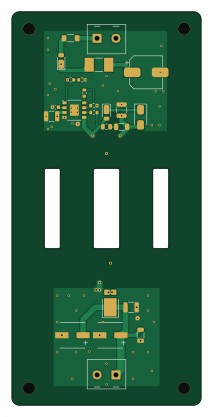
About the 18-36 V to isolated 5 V / 1 A planar flyback PCB
18-36 V to isolated 5 V / 1 A planar flyback is an open source PCB design by jonahsaunders, published on GitHub under the MIT license. It is a 6-layer board measuring 50 × 104 mm, with 25 components from 22 distinct parts.
Other key parts include the LT8302IS8E#PBF. By type, the board carries 8 capacitors, 8 resistors, 4 diodes, 2 connectors, 1 IC and 1 fuse.
It belongs with the rf & radio designs in this gallery.
From the project
KiCad extension for the copper you can't buy as a part — design planar inductors, transformers, PCB motor stators, filters, and antennas, with electrical modeling and direct write-back to your board.
18–36 V DC → isolated 5 V / 1 A. An LT8302 regulates the output through a 4:2 planar transformer built into the six-layer PCB. The 50 × 104 mm board uses a prepared N87 core pair with a 0.21 mm center-leg gap.
A1 engineering prototype — unbuilt and untested. The electronic BOM is fully stocked in the September 30, 2026 JLCPCB snapshot. Factory process acceptance and physical qualification remain open; this is not a production release.
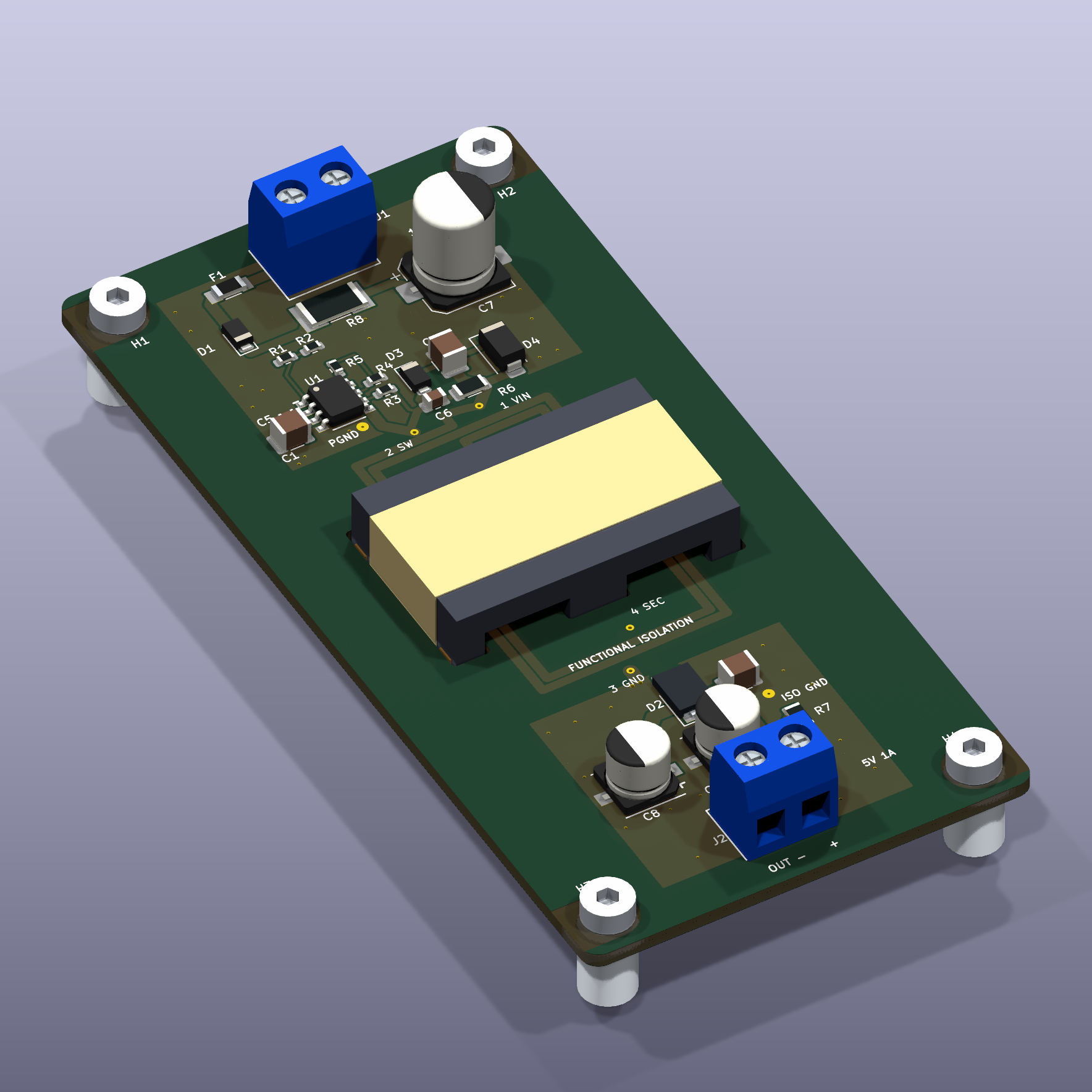
Main components on the 18-36 V to isolated 5 V / 1 A planar flyback
18-36 V to isolated 5 V / 1 A planar flyback bill of materials (BOM)
25 components, 22 distinct parts — part numbers from the project's BOM.
| Qty | Part | Footprint | Refs |
|---|---|---|---|
| 1 | LT8302IS8E#PBF Analog Devices | SOIC8_EP_LT_S8E | U1 |
| 1 | KF301-5.0-2P 18-36 V DC Cixi Kefa | Terminal_KF301_2P_5.00 | J1 |
| 1 | KF301-5.0-2P 5 V / 1 A isolated Cixi Kefa | Terminal_KF301_2P_5.00 | J2 |
| 1 | SF-1206F100-2 1 A / 63 V DC fast Bourns | Fuse_Bourns_SF1206F | F1 |
| 1 | PS-MAG-001 A0 PLANAR 4:2 / Lm 12uH Prepared core assembly to drawing | Planar_EELP32_4T_2T | T1 |
| 2 | DFLS1100-7 Diodes Incorporated | D_PowerDI-123 | D1, D3 |
| 1 | PDS835L-13 Diodes Incorporated | D_PowerDI-5 | D2 |
| 1 | SMAJ12A-13-F Diodes Incorporated | D_SMA | D4 |
| 2 | CL32B106KBJNNNE 10u 50V X7R Samsung Electro-Mechanics | C_1210_3225Metric | C1, C2 |
| 2 | 16SVPF180M 180u 16V Panasonic | CP_Panasonic_C6 | C3, C8 |
| 1 | CL32B226KOJNNNE 22u 16V X7R Samsung Electro-Mechanics | C_1210_3225Metric | C4 |
| 1 | GRM188R61C475KE11D 4.7u / 16 V X5R Murata | C_0603_1608Metric | C5 |
| 1 | CC0805JRNPO0BN471 470p / 100 V C0G Yageo | C_0805_2012Metric | C6 |
| 1 | EEHZC1J470P 47u / 63 V Panasonic | CP_Elec_8x10.5 | C7 |
| 1 | RC0603FR-07649KL 649k 1% Yageo | R_0603_1608Metric | R1 |
| 1 | RC0603FR-0761K9L 61.9k 1% Yageo | R_0603_1608Metric | R2 |
| 1 | RT0603BRD07113KL 113k 0.1% Yageo | R_0603_1608Metric | R3 |
| 1 | RT0603BRD0710K7L 10.7k 0.1% Yageo | R_0603_1608Metric | R4 |
| 1 | RT0603BRD07127KL 127k 0.1% Yageo | R_0603_1608Metric | R5 |
| 1 | SR1206FR-7T39RL 39R 0.75 W Yageo | R_1206_3216Metric | R6 |
Show 2 more
| Qty | Part | Footprint | Refs |
|---|---|---|---|
| 1 | RC1206FR-07220RL 220R 0.25 W Yageo | R_1206_3216Metric | R7 |
| 1 | CRM2512-JW-2R2ELF 2.2R 2 W Bourns | R_Bourns_CRM2512 | R8 |
18-36 V to isolated 5 V / 1 A planar flyback design files
The KiCad project lives in the jonahsaunders/planar-studio repository on GitHub; these links point at the commit this page was built from.
18-36 V to isolated 5 V / 1 A planar flyback: common questions
How big is the 18-36 V to isolated 5 V / 1 A planar flyback PCB?
The 18-36 V to isolated 5 V / 1 A planar flyback measures 50 × 104 mm, has 6 copper layers and is 1.618 mm thick.
How many components are on the 18-36 V to isolated 5 V / 1 A planar flyback?
25 components, from 22 distinct parts, with part numbers taken from the project's own BOM. The full bill of materials is listed on this page.
Where can I download the 18-36 V to isolated 5 V / 1 A planar flyback design files?
From the jonahsaunders/planar-studio repository on GitHub, which has the KiCad layout, the schematic and the BOM; the links under Design files point to each one.
Can I use the 18-36 V to isolated 5 V / 1 A planar flyback design in my own project?
Yes, under the terms of its MIT license, which jonahsaunders chose for the repository.
Similar boards
Hat
pa3gsb
65 × 56 mm81 parts2LNo license675
Radioberry juice
65 × 56 mm87 parts2LNo license675
Radioberry preamp
65 × 56 mm137 parts2LNo license675
Goodwatch20
travisgoodspeed
25.6 × 27.6 mm20 parts2LNo license568
GoodPocketWatch
75.2 × 101.2 mm56 parts2LNo license568
Goodwatch31
25.6 × 27.6 mm23 parts2LNo license568