
Sandy Base

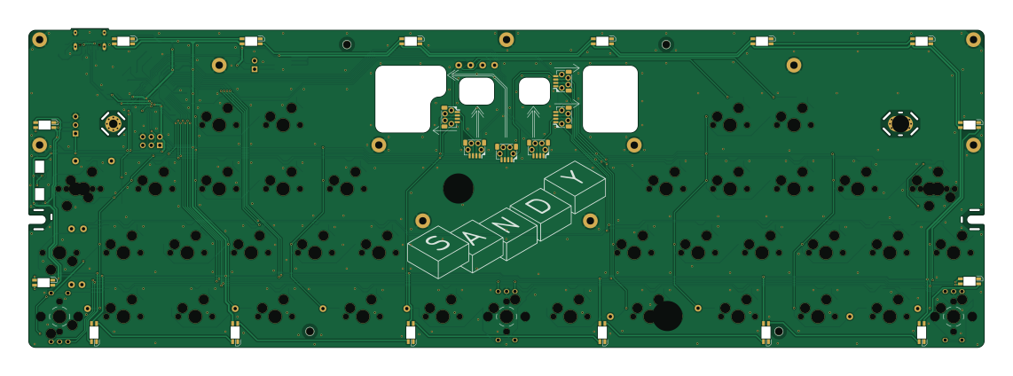
About the Sandy Base PCB
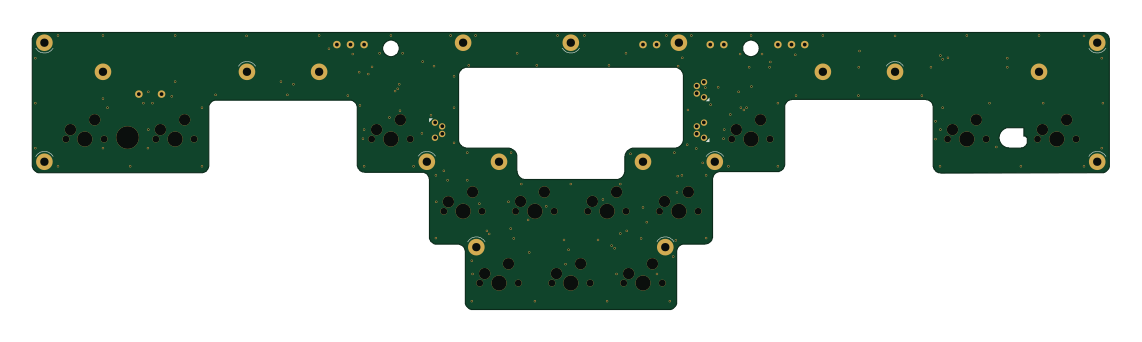
Sandy Base is an open source AVR/Arduino PCB design by jpskenn, published on GitHub under the MIT license. It is a 2-layer board measuring 285 × 95.1 mm, with 153 components from 28 distinct parts.
Its main chip is the ATMEGA32U4-MU, from the AVR/Arduino family. Other key parts include the 24LC64. By type, the board carries 40 diodes, 18 inductors, 10 connectors, 9 capacitors, 8 resistors and 2 ICs.
It belongs with the keyboards designs in this gallery.
From the project
a Keyboard with key height optimization
Sandy is a keyboard with key height optimization.
Layered PCB will make height differences for each key. This covers the lack of optimization to physical key layout that only adjust x-y direction in a plane.
Sandyは、スイッチの配置を立体的にして高さ方向への最適化を加えた、左右対称レイアウトの60%キーボードです。
平面上のキーレイアウトだけでは最適化しきれない部分を、キーの位置に応じてスイッチを配置する高さを変えることで補っています。
キー割り当て書き換えツールRemapがQMKファームウェアのバージョン 0.22.2以降に対応したことに伴い、新しくビルドしたSandyのファームウェアを公開しました。 参考:Remap supports QMK Firmware 0.22.2 or higher
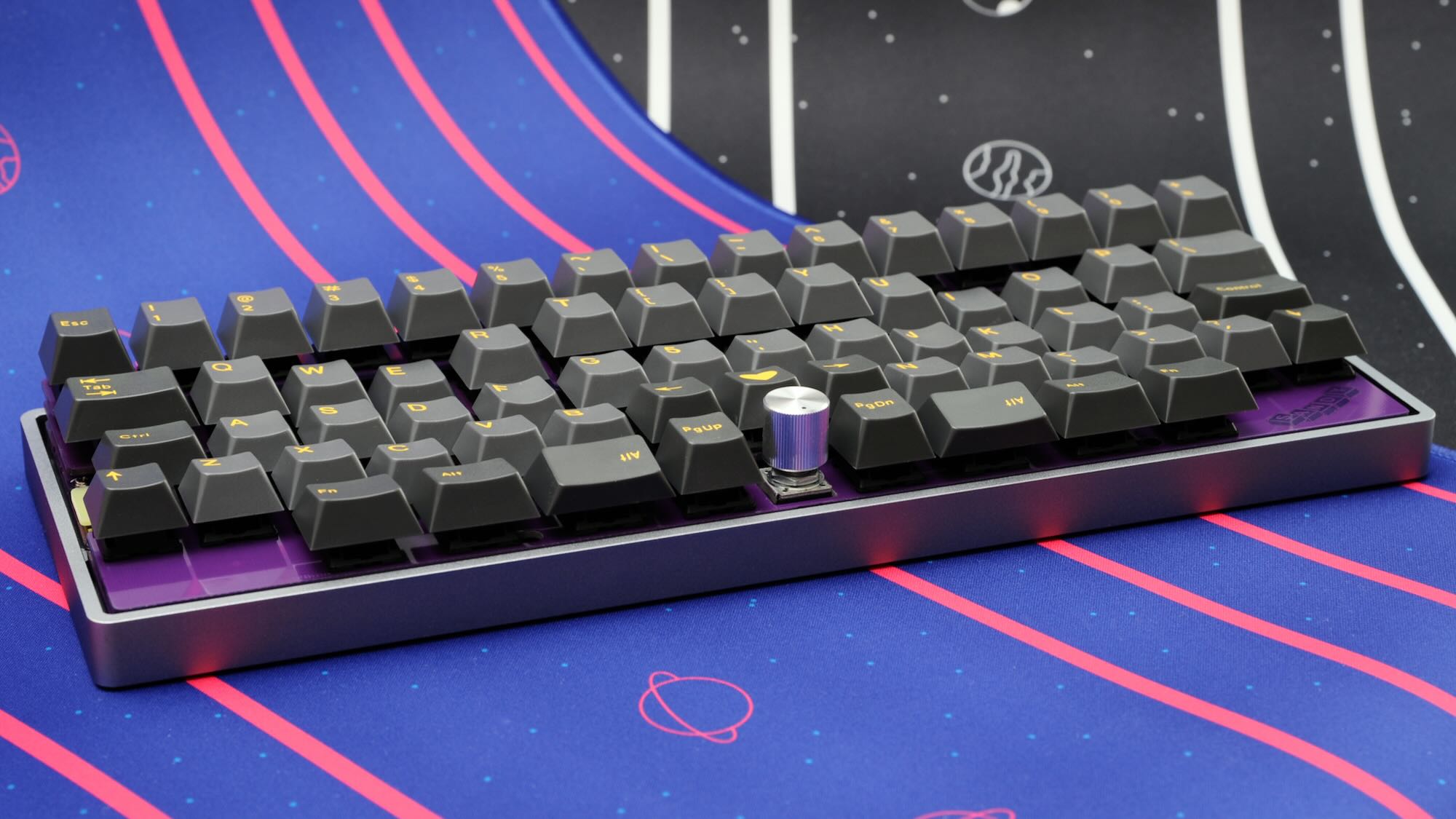
Main components on the Sandy Base
Sandy Base bill of materials (BOM)
153 components, 28 distinct parts — part numbers from the project's BOM.
| Qty | Part | Footprint | Refs |
|---|---|---|---|
| 1 | ATMEGA32U4-MU ATmega32U4-MU | QFN-44-1EP_7x7mm_P0.5mm_EP5.2x5.2mm | U1 |
| 1 | 24LC64 | SO-8_3.9x4.9mm_P1.27mm | U2 |
| 1 | 16MHZ 16MHz | Crystal_SMD_3225-4Pin_3.2x2.5mm_HandSoldering | Y1 |
| 6 | CONN_02X02_TOP_BOTTOM Conn_02x02_Top_Bottom | JST_SH_SM04B-SRSS-TB_1x04-1MP_P1.00mm_Horizontal_wCable_housing_spare_pin | J1, J2, J3, J4, J5, J6 |
| 1 | USB_C_RECEPTACLE_USB2.0 USB_C_Receptacle_USB2.0 | USB_C_Receptacle_HRO_TYPE-C-31-M-12 | J7 |
| 1 | CONN_02X03_ODD_EVEN Conn_02x03_Odd_Even | PinHeader_2x03_P2.54mm_Vertical | J8 |
| 1 | CONN_01X02 Conn_01x02 | PinHeader_1x02_P2.54mm_Vertical | J9 |
| 1 | CONN_01X03 Conn_01x03 | PinHeader_1x03_P2.54mm_Vertical | J10 |
| 18 | Conn_01x01 | TestPoint_THTPad_D2.0mm_Drill1.0mm | EXT_C0, EXT_C1, EXT_C2, EXT_C3, EXT_C4, EXT_C5, EXT_C6, EXT_C7 +10 |
| 1 | 500MA 500mA | Fuse_1206_3216Metric_Pad1.42x1.75mm_HandSolder | F1 |
| 1 | SOLDERJUMPER_3_OPEN SolderJumper_3_Open | SolderJumper-3_P1.3mm_Open_RoundedPad1.0x1.5mm | JP1 |
| 3 | RotaryEncoder_Switch | RotaryEncoder_Alps_EC11K-Switch_Vertical_H20mm_NPTH_MP_minimal | RE_L1, RE_L2, RE_R1 |
| 1 | 5.2X5.2MM 5.2x5.2mm | SW_SPST_TL3342 | ResetSW1 |
| 28 | SW_Push | MXOnly-1U-Hotswap-guide | SW_;1, SW_<1, SW_>1, SW_A1, SW_C1, SW_CenterL1u2, SW_CenterR1u2, SW_D1 +20 |
| 3 | SW_Push | MXOnly-1U-Hotswap-on-RE-guide | SW_CAPS1u1, SW_CenterC1u1, SW_RIGHT1 |
| 4 | SW_Push | MXOnly-1.5U-Hotswap-guide | SW_CTL1.5u1, SW_ENT1.5u1, SW_LSPC1.5u1, SW_RSPC1.5u1 |
| 6 | SW_Push | MXOnly-1.25U-Hotswap-guide | SW_CTL1.25u1, SW_ENT1.25u1, SW_LALT1.25u1, SW_LWIN1.25u1, SW_RALT1.25u1, SW_ROPT1.25u1 |
| 39 | C81598 D | D_SOD-123_Emphasized_Direction_Line_Reference_on_bottom | D1, D2, D3, D4, D5, D6, D7, D8 +31 |
| 1 | PRTR5V0U2X | SOT-143_Handsoldering | D99 |
| 18 | SK6812MINI-E | YS-SK6812MINI-E_middle_hole_with_small_pad | L1, L2, L3, L4, L5, L6, L7, L8 +10 |
Show 8 more
| Qty | Part | Footprint | Refs |
|---|---|---|---|
| 1 | 10UF 10uF | C_0805_2012Metric | C1 |
| 2 | 22PF 22pF | C_0805_2012Metric | C2, C3 |
| 5 | 0.1UF 0.1uF | C_0805_2012Metric | C4, C5, C7, C8, C9 |
| 1 | 1UF 1uF | C_0805_2012Metric | C6 |
| 2 | 5.1K 5.1k | R_0805_2012Metric | R1, R2 |
| 2 | 22 | R_0805_2012Metric | R3, R4 |
| 2 | 10K 10k | R_0805_2012Metric | R5, R6 |
| 2 | 4.7K 4.7k | R_0805_2012Metric | R8, R9 |
Sandy Base design files
The KiCad project lives in the jpskenn/Sandy repository on GitHub; these links point at the commit this page was built from.
Sandy Base: common questions
What microcontroller does the Sandy Base use?
The Sandy Base is built around the ATMEGA32U4-MU, from the AVR/Arduino family.
How big is the Sandy Base PCB?
The Sandy Base measures 285 × 95.1 mm, has 2 copper layers and is 1.6 mm thick.
How many components are on the Sandy Base?
153 components, from 28 distinct parts, with part numbers taken from the project's own BOM. The full bill of materials is listed on this page.
Where can I download the Sandy Base design files?
From the jpskenn/Sandy repository on GitHub, which has the KiCad layout, the schematic and the BOM; the links under Design files point to each one.
Can I use the Sandy Base design in my own project?
Yes, under the terms of its MIT license, which jpskenn chose for the repository.
Can I test firmware for the Sandy Base without the hardware?
Yes. HardLabs builds a simulation of the board from its netlist and BOM, so you can run and debug AVR/Arduino firmware against it before you order a PCB.
More boards in Sandy


Similar boards
 AVR/Arduino
Magspoof
samyk
35 × 29 mm11 parts2LNo license4.2k AVR/Arduino
Redox keyboard
mattdibi
162.2 × 126.5 mm77 parts2LMIT2.0k AVR/Arduino
Labrador
espotek-org
36.8 × 34.7 mm75 parts2LNo license1.2k AVR/Arduino
ModuleV450
stuartpittaway
30 × 61.4 mm39 parts2LCC-BY-NC-4.01.1k AVR/Arduino
V4
30 × 50 mm38 parts2LCC-BY-NC-4.01.1k AVR/Arduino
Discipline
coseyfannitutti
304.9 × 122.8 mm170 parts2LCC-BY-NC-4.01.0k