
Cable Test Master

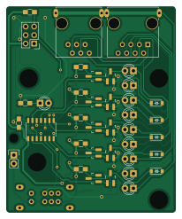
About the Cable Test Master PCB
Cable Test Master is an open source AVR/Arduino PCB design by juniperlynx, published on GitHub under the MIT license. It is a 2-layer board measuring 50.8 × 61.6 mm, with 59 components from 16 distinct parts.
Its main chip is the ATTINY24-SS, from the AVR/Arduino family. Other key parts include the 78L05. By type, the board carries 18 transistors, 12 resistors, 10 LEDs, 9 diodes, 4 connectors and 3 capacitors.
From the project
Simple RJ45/RJ12 cable tester using ATtiny24
Schematics and PCB layouts are available for both ends. The current revision of the Gerbers is untested but only contains slight variations from the most recently ordered version. Complete BOMs for both the master and remote ends are now available for both ends along with Digikey shoping carts in .csv format. I haven't been able to find a source for the multi-LED standoffs used to space the strand indicator LEDs so I've modeled a part in OpenSCAD. The OpenSCAD source and a rendered .stl file are available but untested at this time.
Main components on the Cable Test Master
Cable Test Master bill of materials (BOM)
59 components, 16 distinct parts.
| Qty | Part | Footprint | Refs |
|---|---|---|---|
| 1 | ATTINY24-SS | SOIC-14_3.9x8.7mm_Pitch1.27mm | U1 |
| 1 | 78L05 | 78L05_SOIC | U2 |
| 9 | BSS84 | SOT-23_Handsoldering | Q1, Q2, Q3, Q4, Q5, Q6, Q7, Q8 +1 |
| 9 | 2N7002 | SOT-23_Handsoldering | Q10, Q11, Q12, Q13, Q14, Q15, Q16, Q17 +1 |
| 1 | RJ45 | RJ45_SHLD | J1 |
| 1 | RJ12 | RJ12_SHLD | J2 |
| 1 | PWR | Pin_Header_Straight_1x02 | J3 |
| 1 | ISP | Pin_Header_Straight_2x03 | J4 |
| 1 | DP3T | SW_DP3T_SLIDE | SW1 |
| 10 | LED | LED-3MM | LED1, LED2, LED3, LED4, LED5, LED6, LED7, LED8 +2 |
| 9 | D | SOD-123 | D1, D2, D3, D4, D5, D6, D7, D8 +1 |
| 2 | 1u | C_0805_HandSoldering | C1, C2 |
| 1 | 0.1u | C_0805_HandSoldering | C3 |
| 9 | 200 | R_0805_HandSoldering | R1, R2, R3, R4, R5, R6, R7, R8 +1 |
| 1 | 1K | R_0805_HandSoldering | R10 |
| 2 | 10K | R_0805_HandSoldering | R11, R12 |
Cable Test Master design files
The KiCad project lives in the juniperlynx/Cable-Tester repository on GitHub; these links point at the commit this page was built from.
Cable Test Master: common questions
What microcontroller does the Cable Test Master use?
The Cable Test Master is built around the ATTINY24-SS, from the AVR/Arduino family.
How big is the Cable Test Master PCB?
The Cable Test Master measures 50.8 × 61.6 mm, has 2 copper layers and is 1.6 mm thick.
How many components are on the Cable Test Master?
59 components, from 16 distinct parts. The full bill of materials is listed on this page.
Where can I download the Cable Test Master design files?
From the juniperlynx/Cable-Tester repository on GitHub, which has the KiCad layout; the links under Design files point to each one.
Can I use the Cable Test Master design in my own project?
Yes, under the terms of its MIT license, which juniperlynx chose for the repository.
Can I test firmware for the Cable Test Master without the hardware?
Yes. HardLabs builds a simulation of the board from its netlist and BOM, so you can run and debug AVR/Arduino firmware against it before you order a PCB.
More boards in Cable-Tester
Similar boards
 AVR/Arduino
Redox keyboard
mattdibi
162.2 × 126.5 mm77 parts2LMIT2.0k AVR/Arduino
ModuleV450
stuartpittaway
30 × 61.4 mm39 parts2LCC-BY-NC-4.01.1k AVR/Arduino
V4
30 × 50 mm38 parts2LCC-BY-NC-4.01.1k AVR/Arduino
Discipline
coseyfannitutti
304.9 × 122.8 mm170 parts2LCC-BY-NC-4.01.0k AVR/Arduino
Megadesk
gcormier
41.7 × 32.2 mm23 parts2LGPL-3.0818 AVR/Arduino
Easyduino Atmega Nano
Hanqaqa
43.4 × 18 mm30 parts4LCERN-OHL-P-2.0746