
T41-RF-board-V012

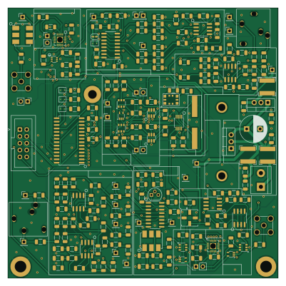
About the T41-RF-board-V012
T41-RF-board-V012 is an open source PCB design by K0RGI, published on GitHub under the GPL-3.0 license. It is a 4-layer board measuring 100 × 100 mm, with 225 components from 61 distinct parts.
Other key parts include the 74CBTLV3253DR, PSA-8A+, PE4312, SN74LVC1G04DCK and MC33078. By type, the board carries 84 capacitors, 63 resistors, 25 ICs, 18 test points, 14 inductors and 6 connectors.
From the project
This is the repository for the officially released V10, V11, and V12 versions of the T41 Software Defined Transceiver hardware and kits. Please read the areas below to understand this project, order boards, make your own boards, find build part lists (BOMs), order kits, and docum
This is the repository for the officially released V10, V11, and V12 versions of the T41 Software Defined Transceiver hardware and kits. Please read the areas below to understand this project, order boards, make your own boards, find build part lists (BOMs), order kits, and documentation that supports the T41 project.
Main components on the T41-RF-board-V012
T41-RF-board-V012 bill of materials (BOM)
225 components, 61 distinct parts — part numbers from the project's BOM.
| Qty | Part | Footprint | Refs |
|---|---|---|---|
| 2 | 74CBTLV3253DR | SOIC-16_3.9x9.9mm_P1.27mm | U1, U4 |
| 1 | PSA-8A+ | SOT-363_SC-70-6 | U2 |
| 2 | PE4312 | PE4312-QFN-20 | U3, U12 |
| 3 | SN74LVC1G04DCK | SOT-SC70 | U5, U10, U18 |
| 4 | MC33078 | SOIC-8_3.9x4.9mm_P1.27mm | U6, U8, U106, U107 |
| 4 | MASWSS0179 | MASWSS0179-SOT-26 | U7, U9, U19, U20 |
| 1 | Si5351A-B-GT | MSOP-10_3x3mm_P0.5mm | U11 |
| 1 | MAR-3SM+ | Mini-Circuits_WW107 | U13 |
| 1 | LM7805CT | TO-220-3_Vertical | U14 |
| 1 | LM1117T-3.3 | TO-220-3_Vertical | U15 |
| 1 | LM358B | SOIC-8_3.9x4.9mm_P1.27mm | U16 |
| 1 | LM317L | SOIC-8_3.9x4.9mm_P1.27mm | U17 |
| 1 | MCP23017_SO | SOIC-28W_7.5x17.9mm_P1.27mm | U21 |
| 2 | HMC434E | SOT-23-6 | U22, U23 |
| 1 | BS170 | TO-92 | Q1 |
| 1 | ECS-TX053-S3 | Oscillator_ECS_TXO53_S3 | Y1 |
| 1 | 25MHz | Crystal_SMD_HC49-SD_HandSoldering | Y2 |
| 1 | IQ_Out | Jack_3.5mm_STX-3081_Horizontal | J1 |
| 1 | RF_IN | SMA_Amphenol_901-144_Vertical | J2 |
| 1 | RFControl | IDC-Header_2x05_P2.54mm_Vertical | J3 |
Show 41 more
| Qty | Part | Footprint | Refs |
|---|---|---|---|
| 1 | 12-13.8V | TerminalBlock_bornier-2_P5.08mm | J4 |
| 1 | IQ_In | Jack_3.5mm_STX-3081_Horizontal | J5 |
| 1 | RF_OUT | SMA_Amphenol_901-144_Vertical | J6 |
| 3 | TestPoint | PinHeader_1x01_P2.54mm_Vertical | G1, G2, G3 |
| 1 | EA-T220-38E | EAT22038E | H4 |
| 1 | SolderJumper_2_Bridged | SolderJumper-2_P1.3mm_Bridged_RoundedPad1.0x1.5mm | JP2 |
| 2 | AttenuatorBypass | PinHeader_1x02_P2.54mm_Vertical | JP3, JP13 |
| 1 | CAL isolation | PinHeader_1x02_P2.54mm_Vertical | JP4 |
| 2 | PrescalarBypass | PinHeader_1x02_P2.54mm_Vertical | JP18, JP19 |
| 18 | TestPoint | PinHeader_1x01_P2.54mm_Vertical | TP1, TP2, TP3, TP4, TP5, TP6, TP7, TP8 +10 |
| 1 | ADT1-1 | Mini-Circuits_CD542_H2.84mm | TR1 |
| 1 | ADT2-1T | Mini-Circuits_CD542_H2.84mm | TR2 |
| 9 | FB | R_1206_3216Metric | L1, L2, L3, L5, L6, L7, L8, L9 +1 |
| 2 | 1.5uH | R_1206_3216Metric | L4, L10 |
| 3 | 10uH 20% | L_Bourns-SRN6028 | L11, L12, L13 |
| 17 | 10uF 50V | C_1206_3216Metric | C1, C3, C11, C12, C14, C32, C35, C36 +9 |
| 4 | 1uF 50V | C_1206_3216Metric | C2, C9, C15, C24 |
| 6 | 10nF 50V | C_1206_3216Metric | C4, C10, C17, C28, C37, C54 |
| 4 | 68pF 50V | C_1206_3216Metric | C5, C8, C19, C21 |
| 42 | 0.1uF 50V | C_1206_3216Metric | C6, C7, C13, C16, C18, C20, C22, C23 +34 |
| 2 | 2.2nF 50V | C_1206_3216Metric | C33, C46 |
| 4 | 0.2uF 50V | C_1206_3216Metric | C34, C38, C44, C50 |
| 1 | 470uF 25V | CP_Radial_D10.0mm_P5.00mm | C69 |
| 4 | 100pF | C_1206_3216Metric | C76, C78, C81, C82 |
| 2 | 2k | R_1206_3216Metric | R1, R13 |
| 8 | 5k1 | R_1206_3216Metric | R2, R3, R5, R6, R10, R11, R17, R18 |
| 5 | 100R | R_1206_3216Metric | R4, R8, R16, R22, R54 |
| 14 | 10k | R_1206_3216Metric | R7, R9, R12, R20, R21, R23, R24, R28 +6 |
| 1 | 36R5 | R_1206_3216Metric | R14 |
| 2 | 500R | R_1206_3216Metric | R15, R19 |
| 6 | 10k 1% | R_1206_3216Metric | R25, R29, R32, R36, R41, R46 |
| 10 | 2k2 | R_1206_3216Metric | R26, R34, R49, R50, R51, R52, R60, R61 +2 |
| 4 | 49R9 1% | R_1206_3216Metric | R27, R33, R38, R43 |
| 2 | 2k2 1% | R_1206_3216Metric | R31, R45 |
| 2 | 3k3 | R_1206_3216Metric | R35, R37 |
| 2 | 0 | R_1206_3216Metric | R40, R42 |
| 1 | 100k | R_1206_3216Metric | R48 |
| 1 | 1k8 | R_1206_3216Metric | R56 |
| 1 | 330R | R_1206_3216Metric | R57 |
| 1 | 51k | R_1206_3216Metric | R58 |
| 1 | 1k2 | R_1206_3216Metric | R59 |
T41-RF-board-V012 design files
The KiCad project lives in the K0RGI/T41-K9HZ repository on GitHub; these links point at the commit this page was built from.
T41-RF-board-V012: common questions
How big is the T41-RF-board-V012?
The T41-RF-board-V012 measures 100 × 100 mm, has 4 copper layers and is 1.6458 mm thick.
How many components are on the T41-RF-board-V012?
225 components, from 61 distinct parts, with part numbers taken from the project's own BOM. The full bill of materials is listed on this page.
Where can I download the T41-RF-board-V012 design files?
From the K0RGI/T41-K9HZ repository on GitHub, which has the KiCad layout, the schematic and the BOM; the links under Design files point to each one.
Can I use the T41-RF-board-V012 design in my own project?
Yes, under the terms of its GPL-3.0 license, which K0RGI chose for the repository.
More boards in T41-K9HZ
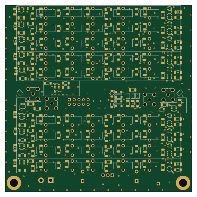
T41-exciter filter board
100 × 100 mm210 parts2LGPL-3.01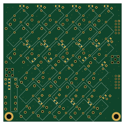
K9HZ 100W 11band LPF-Filter
100 × 100 mm167 parts4LGPL-3.01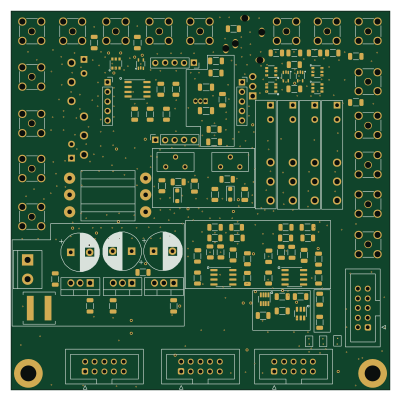
K9HZ 100W 11band LPF-Control
100 × 100 mm150 parts4LGPL-3.01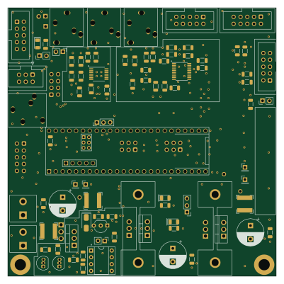 AVR/Arduino
T41-main board-V012
100 × 100 mm95 parts4LGPL-3.01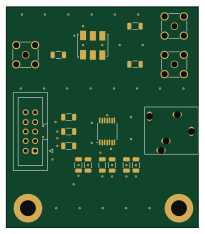
T41-Second receiver adapter
50.8 × 58.4 mm19 parts2LGPL-3.01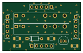
K9HZ 100W 11band LPF-TR-carrier
40.6 × 25.4 mm12 parts2LGPL-3.01