
Rp adapter

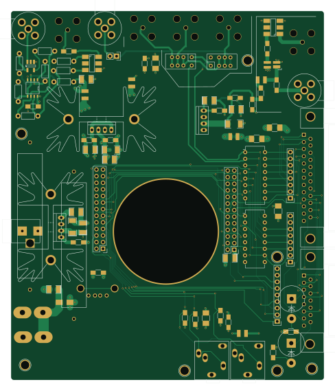
About the Rp adapter PCB
Rp adapter is an open source PCB design by ka6s, published on GitHub under the Custom license license. It is a 4-layer board measuring 120.6 × 142 mm, with 92 components from 53 distinct parts.
Other key parts include the CY8C5868LTI-LP039, CY8C4247AZI-M485, MAX2611, OPA26741C and KA278R05. By type, the board carries 30 capacitors, 18 connectors, 16 resistors, 9 ICs, 5 inductors and 3 transformers.
It belongs with the rf & radio and dev boards & breakouts designs in this gallery.
From the project
Red Pitaya Shield for HPSDR 1W Transceiver. Controls EB104.ru Hermes RX filter, 300W PA Transmit filter.
This is the layout of the 4th iteration of this board. Currently the design in this directory is the transceiver consisting of a connector to the Red Pitaya, the OpenHPSDR TAPR LPU, the OpenHPSDR TAPR T/R board, a 1W PA taken from the OpenHPSDR Penelope board, and a simple 18db ish LNA.
The connecitivy is built to interface to an external amplifier, the Hermes RX Filter from EB104.ru and the 300W LPF from EB104.ru. You need to get the amp keying from the EB104.ru LPF board.
Main components on the Rp adapter
Rp adapter bill of materials (BOM)
92 components, 53 distinct parts — part numbers from the project's BOM.
| Qty | Part | Footprint | Refs |
|---|---|---|---|
| 1 | CY8C5868LTI-LP039 ULN2004A | DIP-16_W7.62mm | U1 |
| 1 | CY8C4247AZI-M485 ULN2004A | DIP-16_W7.62mm | U2 |
| 1 | MAX2611 | SOT-143_Handsoldering | U6 |
| 1 | OPA26741C | SOIC-8-N | U7 |
| 2 | KA278R05 | TO-220_4pin_vertical | U8, U9 |
| 1 | KA278R12 | TO-220_4pin_vertical | U10 |
| 2 | PwrPole | RA_POWER_POLE | U11, U12 |
| 1 | BARREL_JACK | BARREL_JACK | CON1 |
| 1 | DB15 | DB15FC | J1 |
| 1 | DB25 | DB25FC | J2 |
| 1 | SMA | SMA_F_RA | J3 |
| 1 | 9-146280-0-02 SMA | SMA_F_RA | J4 |
| 1 | FTSH-105-01-L-DV-K SMA | SMA_F_RA | J5 |
| 2 | JACK_3P | JACK_3P | J6, J7 |
| 2 | CONN_02X13 | Pin_Header_Straight_2x13 | P1, P2 |
| 1 | CONN_01X09 | Pin_Header_Straight_1x09 | P3 |
| 1 | USB_A | USBA_VERT_STVW | P4 |
| 5 | BNC | BNC_VERTICAL | P8, P9, P10, P14, P15 |
| 1 | CONN_01X02 | Pin_Header_Straight_1x02 | P13 |
| 1 | 0ZCH0050FF2G FUSE | Fuse_SMD1206_HandSoldering | F1 |
Show 33 more
| Qty | Part | Footprint | Refs |
|---|---|---|---|
| 2 | HEATSINK | Heatsink_Fischer_SK129-STS_42x25mm_2xDrill2.5mm | HS2, HS3 |
| 2 | RELAY_RF | RF_RELAY | K1, K2 |
| 2 | 1pin | 1pin | REF01, REF55 |
| 2 | RSIP7 | Pin_Header_Straight_1x08 | RS1, RS2 |
| 1 | TC4-LT | TC4-1T | T1 |
| 1 | ADT1.5-1 | ADT1.5-1 | T2 |
| 1 | ADT1-1 | ADT1.5-1 | T3 |
| 1 | MBR0520L ZENER | Diode_P600_Vertical_AnodeUp | D1 |
| 1 | ZENER | Diode_P600_Vertical_AnodeUp | D2 |
| 1 | BLM18SG331TN1D FB | FB | L3 |
| 4 | FB | FB | L4, L5, L6, L7 |
| 1 | C1005X5R1A104K050BA 100uF | C_1210_HandSoldering | C1 |
| 3 | TMK107BJ105KA-T 1uF | C_1210_HandSoldering | C24, C25, C32 |
| 1 | TMK107BJ105KA-T 0.1uF | C_1206_HandSoldering | C31 |
| 2 | C1005X5R1A104K050BA 0.1uF | C_1206_HandSoldering | C33, C34 |
| 10 | 0.1uF | C_1206_HandSoldering | C35, C36, C38, C39, C44, C45, C46, C50 +2 |
| 4 | 10uF | SMD-1210_Pol | C37, C41, C42, C43 |
| 5 | 100uF | SMD-1210_Pol | C40, C53, C54, C55, C57 |
| 3 | 10uF | SMD-2010_Pol | C47, C48, C49 |
| 1 | 1uF | C_1210_HandSoldering | C56 |
| 1 | ERJ-2GEJ472X 1K | R_1206_HandSoldering | R1 |
| 1 | ERJ-2GEJ153X 1K | R_1206_HandSoldering | R2 |
| 1 | ERJ-3GEY0R00V 75 | R_1206_HandSoldering | R13 |
| 1 | ERJ-6GEYJ561V 100 | Resistor_Horizontal_RM7mm | R15 |
| 1 | ERJ-3GEY0R00V 100 | Resistor_Horizontal_RM7mm | R16 |
| 3 | ERJ-3GEY0R00V 1K | Resistor_Horizontal_RM7mm | R17, R18, R20 |
| 1 | ERJ-3GEYJ821V 1K | Resistor_Horizontal_RM7mm | R19 |
| 1 | ERJ-3GEY0R00V 4R99 | Resistor_Horizontal_RM7mm | R21 |
| 1 | ERJ-6GEY0R00V 4R99 | Resistor_Horizontal_RM7mm | R22 |
| 1 | ERJ-3GEYJ472V 2R2 | RES_10W | R23 |
| 1 | ERJ-3GEY0R00V 2R2 | RES_10W | R24 |
| 1 | ERJ-6GEY0R00V 4.7K | R_1206_HandSoldering | R25 |
| 2 | ERJ-3GEY0R00V 4.7K | R_1206_HandSoldering | R26, R27 |
Rp adapter design files
The KiCad project lives in the ka6s/rp_adapter repository on GitHub; these links point at the commit this page was built from.
Rp adapter: common questions
How big is the Rp adapter PCB?
The Rp adapter measures 120.6 × 142 mm, has 4 copper layers and is 1.6 mm thick.
How many components are on the Rp adapter?
92 components, from 53 distinct parts, with part numbers taken from the project's own BOM. The full bill of materials is listed on this page.
Where can I download the Rp adapter design files?
From the ka6s/rp_adapter repository on GitHub, which has the KiCad layout and the BOM; the links under Design files point to each one.
Can I use the Rp adapter design in my own project?
It is published under Custom license, which limits how it may be reused; read the license before building on it.
More boards in rp_adapter
Similar boards
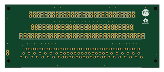
88 Pin Vag Breakout
rusefi
142 × 58 mm91 parts2LGPL-3.01.2k
134pin 7-967288-1
139.7 × 73.7 mm38 parts2LGPL-3.01.2k
Breakout 60pin EEC-IV
139.7 × 62.2 mm15 parts2LGPL-3.01.2k
Breakout 112pin Connector
174 × 58 mm39 parts2LGPL-3.01.2k
Eecv breakout
140.8 × 53.7 mm9 parts4LGPL-3.01.2k
Rj45 breakout
rene-dev
15.2 × 53.8 mm3 parts2LGPL-3.0979