
Phase shifter test board

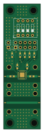
About the Phase shifter test board
Phase shifter test board is an open source STM32 PCB design by kamilix2003, published on GitHub under the MIT license. It is a 2-layer board measuring 19.5 × 65.3 mm, with 17 components from 11 distinct parts.
Its main chip is the STM32G0B1CBTX, from the STM32 family. By type, the board carries 6 connectors, 5 resistors, 4 capacitors, 1 IC and 1 switch.
It belongs with the rf & radio and displays & leds designs in this gallery.
From the project
Interface for RF phase shifter as part of phased antenna array
STM32G0B01 based board for controlling daisy-chained digital phase shifter via SPI-like serial interface. User can interface with the board either by buttons and LEDs on the board or via virtual serial port over USB, communication over serial port is realized using simple TLV protocol. The board is providing bipolar supply for the phase shifters.
Available commands: | Type | Length [bytes] | Value | Description | |----------|--------------------|-----------------------|-------------| | 0x02 | 1 | command id | Ack | | 0x10 | 4 | phase shifts (0 - 15) | Set phase | | 0x11 | 0 | - | Transmit |…
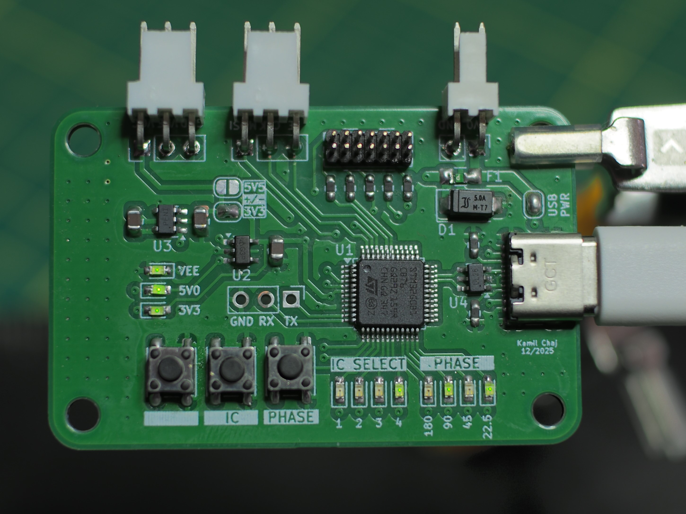
Main components on the Phase shifter test board
Phase shifter test board bill of materials (BOM)
17 components, 11 distinct parts — part numbers from the project's BOM.
| Qty | Part | Footprint | Refs |
|---|---|---|---|
| 1 | STM32G0B1CBTX ~ | QFN-24_EP_4x4_Pitch0.5mm | U1 |
| 1 | CONN_ST_STDC14 ~ | Conn | J1 |
| 1 | USB_C_RECEPTACLE_USB2.0_16P ~ | Conn | J2 |
| 1 | CONN_01X02_PIN ~ | Conn | J3 |
| 1 | CONN_01X03_PIN ~ | Conn | J4 |
| 1 | CONN_01X03_PIN Conn_02x05_Odd_Even | PinHeader_2x05_P2.54mm_Vertical | J5 |
| 1 | CONN_01X03_PIN Conn_01x02_Pin | PinHeader_1x02_P2.54mm_Vertical | J6 |
| 1 | SW_DIP_x04 | SW_DIP_SPSTx04_Slide_9.78x12.34mm_W7.62mm_P2.54mm | SW1 |
| 4 | 4.7U C | C_0603_1608Metric_Pad1.08x0.95mm_HandSolder | C1, C2, C3, C4 |
| 4 | 100 R | R_0603_1608Metric_Pad0.98x0.95mm_HandSolder | R2, R3, R4, R5 |
| 1 | 5.1K R | R_0603_1608Metric_Pad0.98x0.95mm_HandSolder | R7 |
Phase shifter test board design files
The KiCad project lives in the kamilix2003/Phase-Shifter repository on GitHub; these links point at the commit this page was built from.
Phase shifter test board: common questions
What microcontroller does the Phase shifter test board use?
The Phase shifter test board is built around the STM32G0B1CBTX, from the STM32 family.
How big is the Phase shifter test board?
The Phase shifter test board measures 19.5 × 65.3 mm, has 2 copper layers and is 0.491 mm thick.
How many components are on the Phase shifter test board?
17 components, from 11 distinct parts, with part numbers taken from the project's own BOM. The full bill of materials is listed on this page.
Where can I download the Phase shifter test board design files?
From the kamilix2003/Phase-Shifter repository on GitHub, which has the KiCad layout, the schematic and the BOM; the links under Design files point to each one.
Can I use the Phase shifter test board design in my own project?
Yes, under the terms of its MIT license, which kamilix2003 chose for the repository.
Can I test firmware for the Phase shifter test board without the hardware?
Yes. HardLabs builds a simulation of the board from its netlist and BOM, so you can run and debug STM32 firmware against it before you order a PCB.
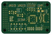
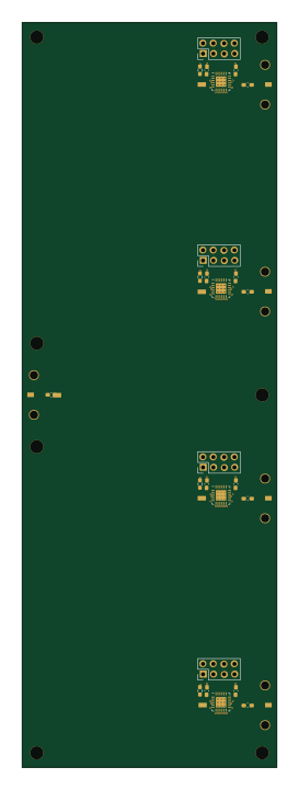
More boards in Phase-Shifter

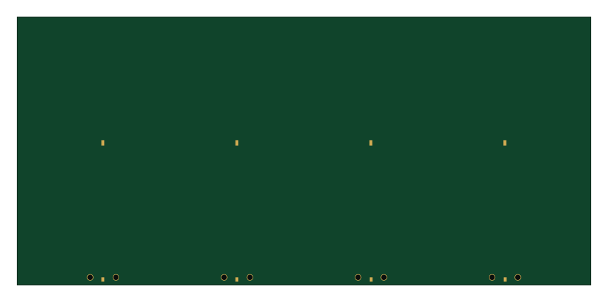

Similar boards
 STM32
LumenPnP Motherboard
opulo-inc
149 × 95 mm296 parts4LCC-BY-SA-4.03.7k STM32
Type g
google
169 × 30 mm24 parts2LApache-2.02.9k STM32
Main panel
234 × 84 mm26 parts4LApache-2.02.9k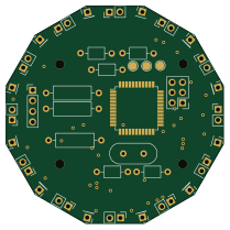 STM32
Base
52.3 × 52.3 mm36 parts2LApache-2.02.9k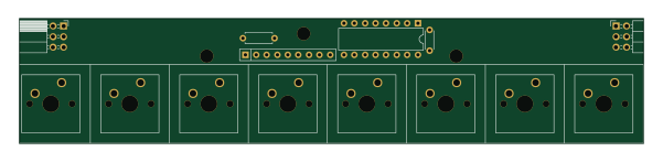 STM32
Type a
150 × 30 mm14 parts2LApache-2.02.9k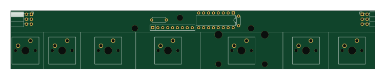 STM32
Type c
188 × 30 mm17 parts2LApache-2.02.9k