
Ledger implant detector

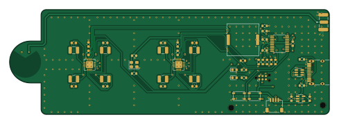
About the Ledger implant detector PCB
Ledger implant detector is an open source STM32 PCB design by KarpelesLab, published on GitHub. It is a 4-layer board measuring 122 × 40 mm, with 53 components from 25 distinct parts.
Its main chip is the STM32F042F6P6, from the STM32 family. Other key parts include the FDC2214RGHR, AP2112K-3.3TRG1 and USBLC6-2SC6. By type, the board carries 19 capacitors, 12 resistors, 8 inductors, 5 ICs, 3 connectors and 2 switches.
From the project
A small hand-held tool for spotting extra conductive structures hidden inside the plastic shell of a hardware wallet (e.g. a Ledger). The target threat is a supply-chain implant that adds a cellular (LTE) modem to the device: such implants need a comparatively large antenna, i.e.
A small hand-held tool for spotting extra conductive structures hidden inside the plastic shell of a hardware wallet (e.g. a Ledger). The target threat is a supply-chain implant that adds a cellular (LTE) modem to the device: such implants need a comparatively large antenna, i.e. a sizeable area of copper that is not present in a genuine unit.
Everything is on one board, powered and programmed over a single USB-C port. No programmer or debug probe is needed (see Programming).
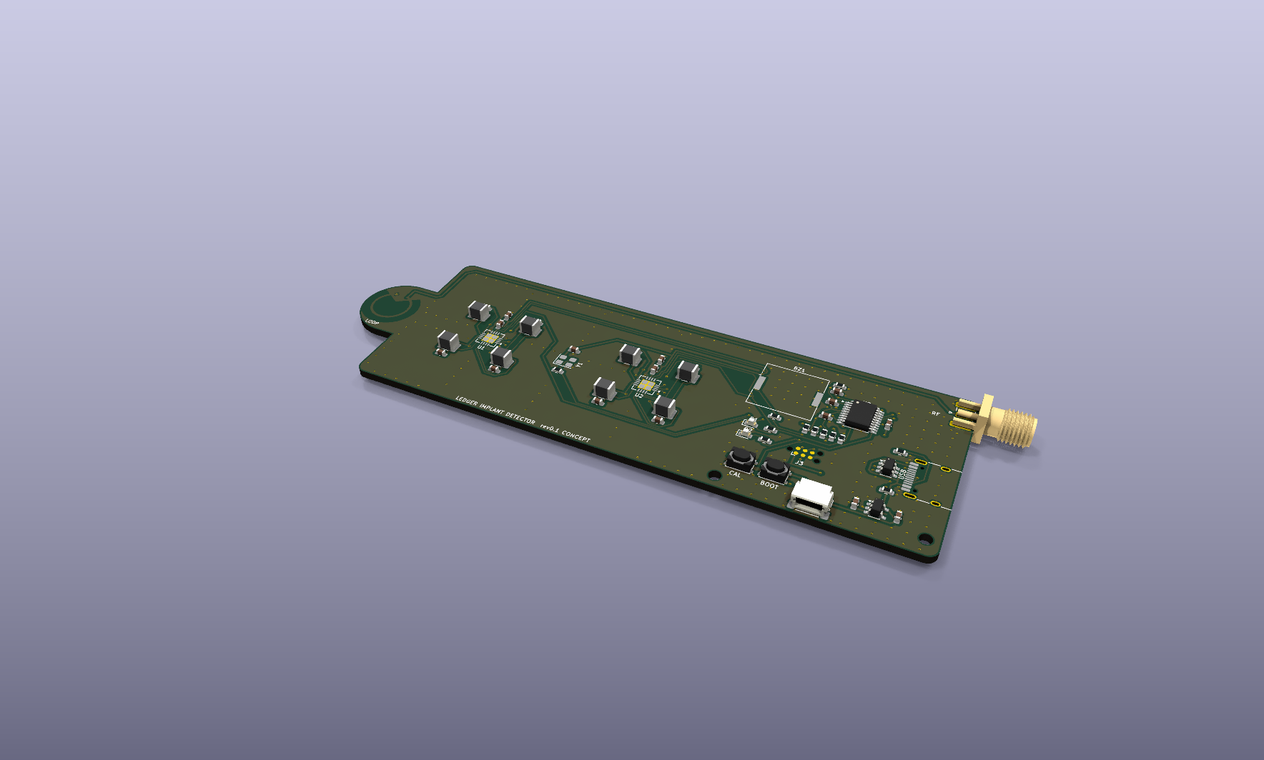
Main components on the Ledger implant detector
Ledger implant detector bill of materials (BOM)
53 components, 25 distinct parts — part numbers from the project's BOM.
| Qty | Part | Footprint | Refs |
|---|---|---|---|
| 2 | FDC2214RGHR FDC2214 Texas Instruments | WQFN-16-1EP_4x4mm_P0.5mm_EP2.6x2.6mm | U1, U2 |
| 1 | STM32F042F6P6 STMicroelectronics | TSSOP-20_4.4x6.5mm_P0.65mm | U3 |
| 1 | AP2112K-3.3TRG1 AP2112K-3.3 Diodes Inc | SOT-23-5 | U4 |
| 1 | USBLC6-2SC6 STMicroelectronics | SOT-23-6 | U5 |
| 1 | ASE-40.000MHZ-LC-T 40MHz Abracon | Oscillator_SMD_Abracon_ASE-4Pin_3.2x2.5mm | Y1 |
| 1 | TYPE-C-31-M-12 USB-C Korean Hroparts Elec | USB_C_Receptacle_HRO_TYPE-C-31-M-12 | J1 |
| 1 | SM04B-SRSS-TB(LF)(SN) Qwiic JST | JST_SH_SM04B-SRSS-TB_1x04-1MP_P1.00mm_Horizontal | J2 |
| 1 | SMA-J-P-H-ST-EM1 SMA Samtec | SMA_Samtec_SMA-J-P-H-ST-EM1_EdgeMount | J4 |
| 1 | PKLCS1212E4001-R1 PKLCS1212E4001 Murata | Buzzer_Murata_PKLCS1212E | BZ1 |
| 1 | PTS810 SJM 250 SMTR LFS CAL C&K | SW_SPST_PTS810 | SW1 |
| 1 | PTS810 SJM 250 SMTR LFS BOOT C&K | SW_SPST_PTS810 | SW2 |
| 1 | 19-217/GHC-YR1S2/3T GREEN Everlight | LED_0603_1608Metric | D1 |
| 1 | 19-217/R6C-AL1M2VY/3T RED Everlight | LED_0603_1608Metric | D2 |
| 8 | CMH322522-180KL 18u Bourns | L_1210_3225Metric | L1, L2, L3, L4, L5, L6, L7, L8 |
| 8 | GRM1885C1H330FA01D 33p Murata | C_0603_1608Metric | C1, C2, C3, C4, C5, C6, C7, C8 |
| 3 | 4.7U 4.7u | C_0603_1608Metric | C9, C10, C13 |
| 6 | 100N 100n | C_0603_1608Metric | C11, C12, C14, C15, C17, C19 |
| 2 | 1u | C_0603_1608Metric | C16, C18 |
| 2 | 5.1K 5.1k | R_0603_1608Metric | R1, R2 |
| 3 | 10K 10k | R_0603_1608Metric | R3, R9, R10 |
Show 5 more
| Qty | Part | Footprint | Refs |
|---|---|---|---|
| 2 | 1k | R_0603_1608Metric | R4, R5 |
| 1 | 100 | R_0603_1608Metric | R6 |
| 2 | 4.7K 4.7k | R_0603_1608Metric | R7, R8 |
| 1 | 100K 100k | R_0603_1608Metric | R11 |
| 1 | 33 | R_0603_1608Metric | R12 |
Ledger implant detector design files
The KiCad project lives in the KarpelesLab/ledger_implant_detector repository on GitHub; these links point at the commit this page was built from.
Ledger implant detector: common questions
What microcontroller does the Ledger implant detector use?
The Ledger implant detector is built around the STM32F042F6P6, from the STM32 family.
How big is the Ledger implant detector PCB?
The Ledger implant detector measures 122 × 40 mm, has 4 copper layers and is 1.6 mm thick.
How many components are on the Ledger implant detector?
53 components, from 25 distinct parts, with part numbers taken from the project's own BOM. The full bill of materials is listed on this page.
Where can I download the Ledger implant detector design files?
From the KarpelesLab/ledger_implant_detector repository on GitHub, which has the KiCad layout, the schematic and the BOM; the links under Design files point to each one.
Can I use the Ledger implant detector design in my own project?
The repository has no license, so all rights stay with KarpelesLab. Use it as a reference, and ask the author before reusing the design.
Can I test firmware for the Ledger implant detector without the hardware?
Yes. HardLabs builds a simulation of the board from its netlist and BOM, so you can run and debug STM32 firmware against it before you order a PCB.
Similar boards
 STM32
LumenPnP Motherboard
opulo-inc
149 × 95 mm296 parts4LCC-BY-SA-4.03.7k STM32
Type g
google
169 × 30 mm24 parts2LApache-2.02.9k STM32
Main panel
234 × 84 mm26 parts4LApache-2.02.9k STM32
Base
52.3 × 52.3 mm36 parts2LApache-2.02.9k STM32
Type a
150 × 30 mm14 parts2LApache-2.02.9k STM32
Type c
188 × 30 mm17 parts2LApache-2.02.9k