Lta power module

About the Lta power module
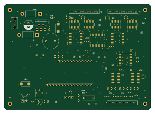
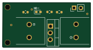
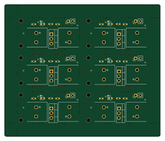
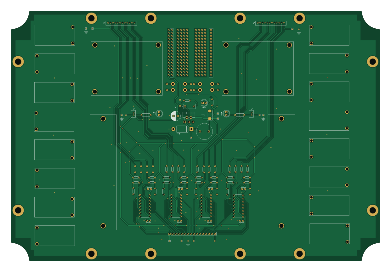
Lta power module is an open source PCB design by kimballa, published on GitHub. It is a 2-layer board measuring 310 × 210 mm, with 283 components from 25 distinct parts.
Other key parts include the DIYMORE_20A_STEP_DOWN, OONO_16A_12POS_TERMINAL_BLOCK, LM2595T-5.0/NOPB and SN75374N. By type, the board carries 197 connectors, 45 resistors, 16 transistors, 10 capacitors, 9 ICs and 4 diodes.
From the project
PCB Schematics for Like The Art project
You Don't Have to Like All the Art! -- PCBs ===========================================
PCB designs and eCAD files for the "You Don't Have to Like All the Art!" project.
This system consists of two distinct circuit boards:
lta-logic-module - The "logic" that determines when it's dark out / should be active, what messages to light up on the sign, manages PWM or other effects when displaying the sign, and also handles button inputs from users. Runs on a combination of 5V and 3V3. This is designed around a port for installing an Adafruit Feather M4 Express (ATSAMD51 / Cortex-M4) Arduino…
Main components on the Lta power module
Lta power module bill of materials (BOM)
283 components, 25 distinct parts — part numbers from the project's BOM.
| Qty | Part | Footprint | Refs |
|---|---|---|---|
| 2 | DIYMORE_20A_STEP_DOWN DIYMORE_20A_Step_Down DIYMORE | 12V_regulator | U1, U2 |
| 2 | OONO_16A_12POS_TERMINAL_BLOCK OONO_16A_12pos_Terminal_Block | 12-way_power_distribution_bus | U3, U4 |
| 1 | LM2595T-5.0/NOPB LM2595T-5 Texas Instruments | TO-220-5_P3.4x3.7mm_StaggerOdd_Lead3.8mm_Vertical-SilkFix | U5 |
| 4 | SN75374N Texas Instruments | TI_N_R-PDIP-T16 | U6, U7, U8, U9 |
| 16 | Dual_MOSFET_Switch_Module | Dual_MOSFET_Driver | Q1, Q2, Q3, Q4, Q5, Q6, Q7, Q8 +8 |
| 2 | 532530270 Molex-MicroLatch-53253-0270 Molex | Molex-MicroLatch-53253-0270 | J1, J2 |
| 2 | 532531270 Molex-MicroLatch-53253-1270 Molex | Molex-MicroLatch-53253-1270 | J3, J4 |
| 1 | 5-146858-1 Conn_01x16 TE Connectivity AMP Connectors | PinHeader_1x16_P2.54mm_Vertical | J5 |
| 184 | CONN_01X01 Conn_01x01 | 1mm_PTH_No_Silk | J6, J8, J9, J10, J11, J12, J13, J14 +176 |
| 8 | CONN_01X01 Conn_01x01 | 1.6mm_PTH_No_Silk | J18, J46, J60, J70, J98, J108, J122, J160 |
| 1 | DS01-254-S-01BE SW_SPST CUI Devices | CUI-DIP-SW_DS01-254-x-01xx | SW1 |
| 1 | C5SMF-RJF-CT0W0BB1 PWR0 CreeLED | LED_D5.0mm_SilkFix | D1 |
| 1 | C5SMF-RJF-CT0W0BB1 PWR1 CreeLED | LED_D5.0mm_SilkFix | D2 |
| 1 | SB530-E3/54 SB530 Vishay | D_DO-201AD_P15.24mm_Horizontal | D3 |
| 1 | C5SMF-RJF-CT0W0BB1 5V0PWR CreeLED | LED_D5.0mm_SilkFix | D4 |
| 1 | AIUR-06-151K 150u Abracon LLC | L_Radial_D13.5mm_P7.50mm | L1 |
| 1 | EST227M035AG4AA 220u KEMET | CP_Radial_D8.0mm_P3.50mm | C1 |
| 1 | TPSD686M020R0150 68u KYOCERA AVX | CP_EIA-7343-30_AVX-N_Pad2.25x2.55mm_HandSolder | C2 |
| 8 | C315C105K3R5TA7303 1u KEMET | C_Disc_D3.8mm_W2.6mm_P2.50mm | C3, C4, C5, C6, C7, C8, C9, C10 |
| 2 | CF14JT1K00 1K, 1/4W Stackpole | R_Axial_DIN0207_L6.3mm_D2.5mm_P7.62mm_Horizontal | R1, R2 |
Show 5 more
| Qty | Part | Footprint | Refs |
|---|---|---|---|
| 2 | CF18JT10K0 10K Stackpole | R_Axial_DIN0204_L3.6mm_D1.6mm_P5.08mm_Horizontal | R3, R4 |
| 1 | CF18JT330R 330R Stackpole | R_Axial_DIN0204_L3.6mm_D1.6mm_P5.08mm_Horizontal | R5 |
| 8 | CF18JT220R 220R Stackpole | R_Axial_DIN0204_L3.6mm_D1.6mm_P5.08mm_Horizontal | R6, R7, R28, R29, R34, R38, R48, R55 |
| 16 | CF18JT2K20 2K2 Stackpole | R_Axial_DIN0204_L3.6mm_D1.6mm_P5.08mm_Horizontal | R8, R9, R10, R11, R24, R25, R26, R27 +8 |
| 16 | CF18JT33R0 33R Stackpole | R_Axial_DIN0204_L3.6mm_D1.6mm_P5.08mm_Horizontal | R12, R13, R14, R15, R20, R21, R22, R23 +8 |
Lta power module design files
The KiCad project lives in the kimballa/like-the-art-pcb repository on GitHub; these links point at the commit this page was built from.
Lta power module: common questions
How big is the Lta power module?
The Lta power module measures 310 × 210 mm, has 2 copper layers and is 1.6 mm thick.
How many components are on the Lta power module?
283 components, from 25 distinct parts, with part numbers taken from the project's own BOM. The full bill of materials is listed on this page.
Where can I download the Lta power module design files?
From the kimballa/like-the-art-pcb repository on GitHub, which has the KiCad layout, the schematic and the BOM; the links under Design files point to each one.
Can I use the Lta power module design in my own project?
The repository has no license, so all rights stay with kimballa. Use it as a reference, and ask the author before reusing the design.