
Gps development boards

About the Gps development boards PCB
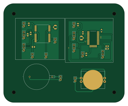
Gps development boards is an open source PCB design by leonardoward, published on GitHub under the Apache-2.0 license. It is a 2-layer board measuring 107 × 88 mm, with 29 components from 13 distinct parts.
Other key parts include the ATGM332D-5N31 and M20050-1. By type, the board carries 17 connectors, 4 capacitors, 4 resistors, 2 ICs, 1 diode and 1 inductor.
It belongs with the rf & radio and dev boards & breakouts designs in this gallery.
From the project
Development Board designed with KiCad for the ANTENOVA M20050-1 and the ATGM332D-5N31
A KiCad breakout board for evaluating two GPS modules side by side — the ANTENOVA M20050-1 and the ATGM332D-5N31 — plus two footprints for 20 mm coin‑cell holders to keep the module's backup RAM / almanac powered for a warm start.
This is one of the breakout boards made for the EJA "Intelligent Popup Buoy" project (2021 Hackaday Dream Team). Each candidate part for the EJA M board was first tried on a small dedicated PCB. Both GPS modules speak plain NMEA over UART and are wired to identical header pinouts here, so the same ESP32 firmware runs against either one.…
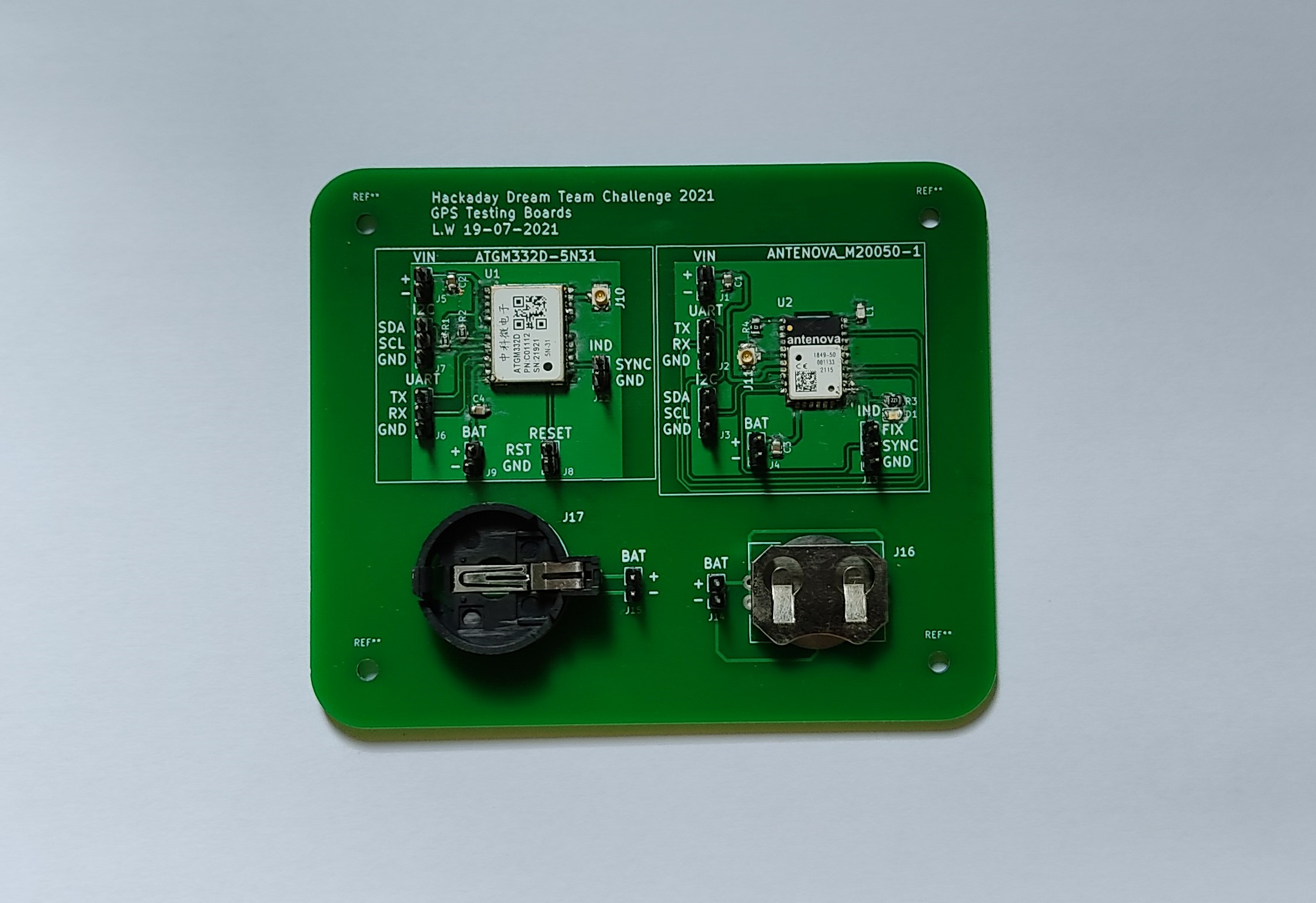
Main components on the Gps development boards
Gps development boards bill of materials (BOM)
29 components, 13 distinct parts.
| Qty | Part | Footprint | Refs |
|---|---|---|---|
| 1 | ATGM332D-5N31 | ATGM332D5N31 | U1 |
| 1 | M20050-1 | M200501 | U2 |
| 8 | Conn_01x02_Male | PinSocket_1x02_P2.54mm_Vertical | J1, J4, J5, J8, J9, J12, J14, J15 |
| 5 | Conn_01x03_Male | PinSocket_1x03_P2.54mm_Vertical | J2, J3, J6, J7, J13 |
| 2 | U.FL-R-SMT-1_10_ | U.FL-R-SMT-1_10_ | J10, J11 |
| 1 | BAT-HLD-001-THM | BATHLD001THM | J16 |
| 1 | 1066 | BAT-1066 | J17 |
| 1 | RED-CLEAR | LED_0805_2012Metric | D1 |
| 1 | 1.8nH | L_0805_2012Metric | L1 |
| 4 | 10uF | C_0805_2012Metric | C1, C2, C3, C4 |
| 2 | 1K | R_0805_2012Metric | R1, R2 |
| 1 | 220 | R_0805_2012Metric | R3 |
| 1 | 0 | R_0805_2012Metric | R4 |
Gps development boards design files
The KiCad project lives in the leonardoward/gps-development-boards repository on GitHub; these links point at the commit this page was built from.
Gps development boards: common questions
How big is the Gps development boards PCB?
The Gps development boards measures 107 × 88 mm, has 2 copper layers and is 1.6 mm thick.
How many components are on the Gps development boards?
29 components, from 13 distinct parts. The full bill of materials is listed on this page.
Where can I download the Gps development boards design files?
From the leonardoward/gps-development-boards repository on GitHub, which has the KiCad layout; the links under Design files point to each one.
Can I use the Gps development boards design in my own project?
Yes, under the terms of its Apache-2.0 license, which leonardoward chose for the repository.
Similar boards
88 Pin Vag Breakout
rusefi
142 × 58 mm91 parts2LGPL-3.01.2k
134pin 7-967288-1
139.7 × 73.7 mm38 parts2LGPL-3.01.2k
Breakout 60pin EEC-IV
139.7 × 62.2 mm15 parts2LGPL-3.01.2k
Breakout 112pin Connector
174 × 58 mm39 parts2LGPL-3.01.2k
Eecv breakout
140.8 × 53.7 mm9 parts4LGPL-3.01.2k
Rj45 breakout
rene-dev
15.2 × 53.8 mm3 parts2LGPL-3.0979