
Home robot

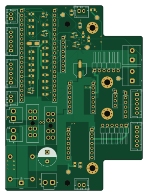
About the Home robot PCB
Home robot is an open source RP2040/RP2350 PCB design by liorknafo, published on GitHub under the MIT license. It is a 4-layer board measuring 73.9 × 100 mm, with 62 components from 40 distinct parts.
Its main chip is the Pico left row, from the RP2040/RP2350 family. Other key parts include the Pico right row, GY-521 MPU-6050, DRV8874 left, VM/EN/PH row, DRV8874 left, VIN/OUT row and DRV8874 right, VM/EN/PH row. By type, the board carries 23 resistors, 15 connectors, 9 ICs, 5 transistors, 3 LEDs and 3 capacitors.
It belongs with the robotics & motion and sensors designs in this gallery.
From the project
R1 round home robot: Jetson Nano, CadQuery CAD, 4-layer power & I/O board (KiCad), Unreal 5.8 simulator and Python autonomy (LiDAR mapping, camera obstacles)
A round (Ø 318 mm, 155 mm tall) differential-drive home robot built around an NVIDIA Jetson Nano, together with the Unreal simulator and the Python autonomy stack it is developed against.
Status: work in progress. Nothing has been ordered or printed yet.
- Compute: Jetson Nano B01 on standoffs over the motors. - Board: a 74 × 100 mm 4-layer power & I/O board under the Jetson. It carries: - a Raspberry Pi Pico for real-time I/O; - two Pololu DRV8874 motor drivers; - a GY-521 (MPU-6050) IMU; - fuses, a relay and connectors. - Sensors: - an LDROBOT LD14 (D200) 2D LiDAR at 147.5 mm; - one…
Main components on the Home robot
Home robot bill of materials (BOM)
62 components, 40 distinct parts — part numbers from the project's BOM.
| Qty | Part | Footprint | Refs |
|---|---|---|---|
| 1 | Pico left row | PinSocket_1x20_P2.54mm_Vertical | U1A |
| 1 | Pico right row | PinSocket_1x20_P2.54mm_Vertical | U1B |
| 1 | GY-521 MPU-6050 | PinSocket_1x08_P2.54mm_Vertical | U2 |
| 1 | DRV8874 left, VM/EN/PH row | PinSocket_1x07_P2.54mm_Vertical | U3L |
| 1 | DRV8874 left, VIN/OUT row | PinSocket_1x07_P2.54mm_Vertical | U3P |
| 1 | DRV8874 right, VM/EN/PH row | PinSocket_1x07_P2.54mm_Vertical | U4L |
| 1 | DRV8874 right, VIN/OUT row | PinSocket_1x07_P2.54mm_Vertical | U4P |
| 1 | Regulator in (P03 module) | TerminalBlock_Phoenix_MKDS-1,5-2-5.08_1x02_P5.08mm_Horizontal | U5A |
| 1 | Regulator out (P03 module) | TerminalBlock_Phoenix_MKDS-1,5-2-5.08_1x02_P5.08mm_Horizontal | U5B |
| 5 | 2N7002 | SOT-23 | Q1, Q2, Q3, Q4, Q5 |
| 1 | Battery in | JST_VH_B2P-VH_1x02_P3.96mm_Vertical | J1 |
| 1 | Master rocker | JST_VH_B2P-VH_1x02_P3.96mm_Vertical | J2 |
| 1 | Jetson 5V | JST_VH_B2P-VH_1x02_P3.96mm_Vertical | J3 |
| 1 | Left motor | PinHeader_1x06_P2.54mm_Horizontal | J4 |
| 1 | Right motor | PinHeader_1x06_P2.54mm_Horizontal | J5 |
| 1 | Cliff 1 | JST_XH_B5B-XH-A_1x05_P2.50mm_Vertical | J6 |
| 1 | Cliff 2 | JST_XH_B5B-XH-A_1x05_P2.50mm_Vertical | J7 |
| 1 | Cliff 3 | JST_XH_B5B-XH-A_1x05_P2.50mm_Vertical | J8 |
| 1 | Cliff 4 | JST_XH_B5B-XH-A_1x05_P2.50mm_Vertical | J9 |
| 1 | Bumper L | JST_XH_B2B-XH-A_1x02_P2.50mm_Vertical | J10 |
Show 20 more
| Qty | Part | Footprint | Refs |
|---|---|---|---|
| 1 | Bumper R | JST_XH_B2B-XH-A_1x02_P2.50mm_Vertical | J11 |
| 1 | Arm button | JST_XH_B2B-XH-A_1x02_P2.50mm_Vertical | J12 |
| 1 | Motor toggle loop | JST_XH_B2B-XH-A_1x02_P2.50mm_Vertical | J13 |
| 1 | Spare I2C | PinHeader_1x04_P2.54mm_Vertical | J14 |
| 1 | Spare GPIO | PinHeader_1x06_P2.54mm_Vertical | J15 |
| 1 | 7.5 A ATO | FuseHolder_Blade_ATO_Littelfuse_FLR_178.6165 | F1 |
| 1 | 5 A ATO | FuseHolder_Blade_ATO_Littelfuse_FLR_178.6165 | F2 |
| 1 | G5LE-1 DC5 | Relay_SPDT_Omron-G5LE-1 | K1 |
| 2 | green | LED_0805_2012Metric | LED1, LED2 |
| 1 | yellow | LED_0805_2012Metric | LED3 |
| 1 | SS14 | D_SMA | D1 |
| 1 | 470uF 25V | CP_Radial_D10.0mm_P5.00mm | C1 |
| 1 | 100nF | C_0805_2012Metric | C2 |
| 1 | 100uF 16V | CP_Elec_6.3x5.8 | C3 |
| 7 | 100k | R_0805_2012Metric | R1, R3, R5, R7, R9, R11, R17 |
| 10 | 10k | R_0805_2012Metric | R2, R4, R6, R8, R10, R13, R14, R15 +2 |
| 1 | 33k | R_0805_2012Metric | R12 |
| 2 | 4.7k | R_0805_2012Metric | R19, R20 |
| 2 | 3.3k | R_0805_2012Metric | R21, R23 |
| 1 | 1k | R_0805_2012Metric | R22 |
Home robot design files
The KiCad project lives in the liorknafo/home-robot repository on GitHub; these links point at the commit this page was built from.
Home robot: common questions
What microcontroller does the Home robot use?
The Home robot is built around the Pico left row, from the RP2040/RP2350 family.
How big is the Home robot PCB?
The Home robot measures 73.9 × 100 mm, has 4 copper layers and is 1.6 mm thick.
How many components are on the Home robot?
62 components, from 40 distinct parts, with part numbers taken from the project's own BOM. The full bill of materials is listed on this page.
Where can I download the Home robot design files?
From the liorknafo/home-robot repository on GitHub, which has the KiCad layout, the schematic and the BOM; the links under Design files point to each one.
Can I use the Home robot design in my own project?
Yes, under the terms of its MIT license, which liorknafo chose for the repository.
Can I test firmware for the Home robot without the hardware?
Yes. HardLabs builds a simulation of the board from its netlist and BOM, so you can run and debug RP2040/RP2350 firmware against it before you order a PCB.
Similar boards
 RP2040/RP2350
Open Book Abridged Edition
joeycastillo
85 × 115 mm29 parts2LCC-BY-SA-4.08.1k RP2040/RP2350
Corne
foostan
277.2 × 107.5 mm164 parts2LCC-BY-4.07.7k RP2040/RP2350
Corne
277.2 × 107.5 mm164 parts2LCC-BY-4.07.7k RP2040/RP2350
Jitx design
gusmanb
55.5 × 65 mm26 parts4LGPL-3.05.0k RP2040/RP2350
LogicAnalyzer
57 × 55.2 mm6 parts2LGPL-3.05.0k RP2040/RP2350
Main
google
98 × 71 mm102 parts2LApache-2.02.9k