
PODD

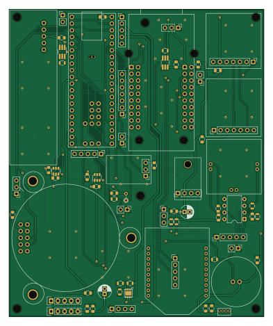
About the PODD PCB
PODD is an open source NXP PCB design by lmnts, published on GitHub. It is a 2-layer board measuring 97 × 117 mm, with 71 components from 43 distinct parts.
Its main chip is the 1568-1232, from the NXP family. Other key parts include the AD822ANZ, 296-46373-1, 602-1301 and 296-30381-1. By type, the board carries 27 connectors, 25 capacitors, 11 resistors, 6 ICs and 2 transistors.
It belongs with the dev boards & breakouts designs in this gallery.
From the project
A tool to understand how buildings perform in terms of occupant comfort. https://lmnarchitects.com/tech-studio/
The Teensy++ 2.0 is used in 3.3V mode in order to save power. Before plugging the teensy in, please do the following:
The files in this repo are for the LMN SensorPod Phase 1 hardware. To open them, you'll need KiCAD:
It may also be helpful to use these libraries:
Main components on the PODD
PODD bill of materials (BOM)
71 components, 43 distinct parts — part numbers from the project's BOM.
| Qty | Part | Footprint | Refs |
|---|---|---|---|
| 1 | AD822ANZ AD822 | DIP-8_W7.62mm | U1 |
| 1 | 296-46373-1 TPS2113A | SON-8 | U2 |
| 1 | 602-1301 XBEE | XBEE | U5 |
| 1 | 1568-1232 TEENSYPP2 | TEENSYPP2 | U6 |
| 2 | 296-30381-1 74LVC1T45 | SOT-23-6 | U9, U10 |
| 2 | NTGD1100LT1GOS NTGD1100L | TSOT-23-6_HandSoldering | Q1, Q2 |
| 1 | 1278-1010 WIZ812MJ | WIZ812MJ | J1 |
| 2 | CONN_01X05 | Pin_Header_Straight_1x05 | J2, J3 |
| 1 | TEST_SPI | Pin_Header_Straight_1x07_Pitch2.54mm | J4 |
| 1 | CONN_01X05 | Pin_Header_Straight_1x05_Pitch2.54mm | J5 |
| 1 | CONN_01X04 | Pin_Header_Straight_1x04_Pitch2.54mm | J7 |
| 1 | TEST_XBEE | Pin_Header_Straight_1x05_Pitch2.54mm | J8 |
| 1 | BOB-12758 CMR-2747PB-A | CMR-2747PB-A | P1 |
| 1 | TEST_PM_EN | Pin_Header_Straight_1x02_Pitch2.54mm | P2 |
| 1 | TEST_ETH_EN | Pin_Header_Straight_1x03_Pitch2.54mm | P3 |
| 1 | 615-1068 PR222J2 | R_Axial_DIN0204_L3.6mm_D1.6mm_P2.54mm_Vertical | P6 |
| 1 | 2745 LM3671 | LM3671 | P7 |
| 1 | SLD-68-026 | SLD-68-026 | P8 |
| 1 | 1684-1000 3SP_CO_1000 | 3SP_CO_1000 | P9 |
| 1 | COZIR-AV-1 COZIR | COZIR | P10 |
Show 23 more
| Qty | Part | Footprint | Refs |
|---|---|---|---|
| 1 | 235-1443 SM-PWM-01C | SM-PWM-01C | P11 |
| 1 | 480-5706-1 HIH8120-021 | HIH8120-021 | P12 |
| 1 | BOB-00544 microSD Transflash | SD_Card | P13 |
| 1 | BOB-10160 DeadOn RTC | DeadOn_RTC | P14 |
| 1 | TEST_NET | Pin_Header_Straight_1x02_Pitch2.54mm | P15 |
| 1 | TEST_AUDIO | Pin_Header_Straight_1x02_Pitch2.54mm | P18 |
| 1 | TEST_LIGHT | Pin_Header_Straight_1x02_Pitch2.54mm | P19 |
| 1 | TEST_TEMP | Pin_Header_Straight_1x02_Pitch2.54mm | P20 |
| 1 | TEST_I2C | Pin_Header_Straight_1x03_Pitch2.54mm | P21 |
| 1 | TEST_PM | Pin_Header_Straight_1x05_Pitch2.54mm | P22 |
| 1 | TEST_CO2 | Pin_Header_Straight_1x03_Pitch2.54mm | P23 |
| 1 | TEST_CO | Pin_Header_Straight_1x05_Pitch2.54mm | P24 |
| 3 | 1276-3022-1 4.7u | C_0805 | C1, C2, C30 |
| 19 | 399-1170-1 0.1u | C_0805 | C3, C4, C6, C7, C8, C9, C10, C11 +11 |
| 1 | 1276-6496-1 0.22u | C_0805 | C5 |
| 2 | 732-8598-1 100u | CP_Radial_D5.0mm_P2.00mm | C16, C18 |
| 4 | 311-10.0KCR 10k | R_0805 | R1, R2, R3, R9 |
| 1 | RMCF0805JT470K 470k | R_0805 | R4 |
| 1 | 311-1.0KAR 1k | R_0805 | R5 |
| 2 | RMCF0805JT2K20 2.2k | R_0805 | R6, R7 |
| 1 | RMCF0805JT150R 150 | R_0805 | R8 |
| 1 | RMCF0805JT3K00 3k | R_0805 | R10 |
| 1 | 311-698CR 698 | R_0805 | R11 |
PODD design files
The KiCad project lives in the lmnts/PODD repository on GitHub; these links point at the commit this page was built from.
PODD: common questions
What microcontroller does the PODD use?
The PODD is built around the 1568-1232, from the NXP family.
How big is the PODD PCB?
The PODD measures 97 × 117 mm, has 2 copper layers and is 0.8 mm thick.
How many components are on the PODD?
71 components, from 43 distinct parts, with part numbers taken from the project's own BOM. The full bill of materials is listed on this page.
Where can I download the PODD design files?
From the lmnts/PODD repository on GitHub, which has the KiCad layout and the BOM; the links under Design files point to each one.
Can I use the PODD design in my own project?
The repository has no license, so all rights stay with lmnts. Use it as a reference, and ask the author before reusing the design.
Can I test firmware for the PODD without the hardware?
Yes. HardLabs builds a simulation of the board from its netlist and BOM, so you can run and debug NXP firmware against it before you order a PCB.
Similar boards
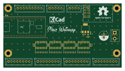 NXP
32Bit shift register
MaltWhiskey
100 × 54 mm56 parts4LNo license763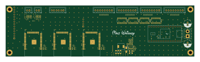 NXP
Mega-Cube-Board
200 × 54 mm100 parts4LNo license763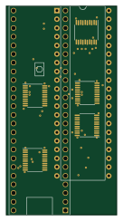 NXP
MCL6809
MicroCoreLabs
32.3 × 61 mm7 parts4LNo license532 NXP
MCL68
31.6 × 84.1 mm13 parts4LNo license532 NXP
MCL65+
72.6 × 64.1 mm6 parts2LNo license532 NXP
MCLZ8
37.1 × 61.5 mm6 parts4LNo license532