
Rom

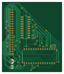
About the Rom PCB
Rom is an open source PCB design by lorenzonotaro, published on GitHub. It is a 2-layer board measuring 65.5 × 77 mm, with 7 components from 6 distinct parts.
Other key parts include the AT28C64B-15PU, LNCPU Type A Header and 74HCT541. By type, the board carries 4 capacitors and 3 ICs.
From the project
v1 is the current implementation of the lncpu.
v1 is the current implementation of the lncpu.
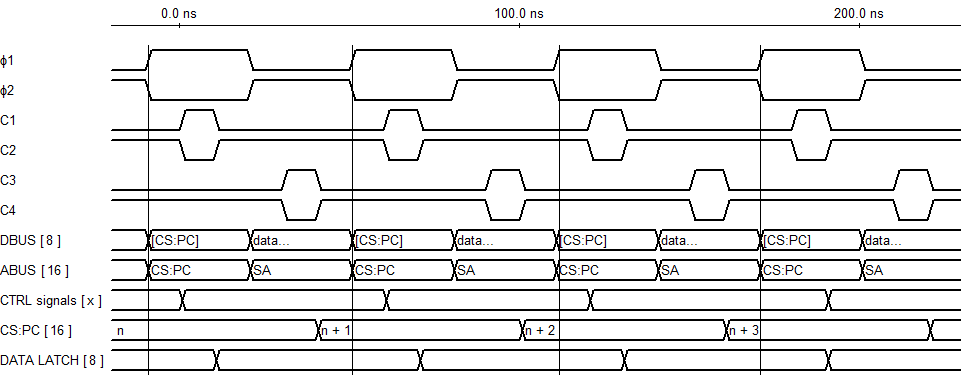
The clock cycle is divided in two phases: Φ1 (control phase) and Φ2 (data phase).
During Φ1, the data bus contains the contents of [CS:PC]: only the device mapped to the memory section containing address CS:PC` is allowed to write to the data bus, regardless of control signals.
* During Φ2, bus control is determined by the control signals of the current microinstruction.
Main components on the Rom
Rom bill of materials (BOM)
7 components, 6 distinct parts.
| Qty | Part | Footprint | Refs |
|---|---|---|---|
| 1 | AT28C64B-15PU | DIP1556W56P254L3702H483Q28N | IC1 |
| 1 | LNCPU Type A Header | LNCPU_Type_A_Header | U1 |
| 1 | 74HCT541 | DIP-20_W7.62mm_LongPads | U2 |
| 2 | 220n | C_Disc_D5.0mm_W2.5mm_P2.50mm | C1, C2 |
| 1 | 47u | CP_Radial_D5.0mm_P2.00mm | C3 |
| 1 | 1u | CP_Radial_D4.0mm_P2.00mm-Large-Holes | C4 |
Rom design files
The KiCad project lives in the lorenzonotaro/lncpu repository on GitHub; these links point at the commit this page was built from.
- Layoutv1/kicad/rom/rom.kicad_pcb
- Schematicv1/kicad/rom/rom.kicad_sch
Rom: common questions
How big is the Rom PCB?
The Rom measures 65.5 × 77 mm, has 2 copper layers and is 1.6 mm thick.
How many components are on the Rom?
7 components, from 6 distinct parts. The full bill of materials is listed on this page.
Where can I download the Rom design files?
From the lorenzonotaro/lncpu repository on GitHub, which has the KiCad layout and the schematic; the links under Design files point to each one.
Can I use the Rom design in my own project?
The repository has no license, so all rights stay with lorenzonotaro. Use it as a reference, and ask the author before reusing the design.
More boards in lncpu

Alu
200 × 150 mm45 parts2LNo license8
Alu base
200 × 150 mm45 parts2LNo license8
Alu operand selector
82.5 × 163.2 mm29 parts2LNo license8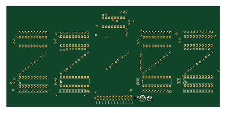
Alu operand selector horizontal
182.2 × 85.5 mm29 parts2LNo license8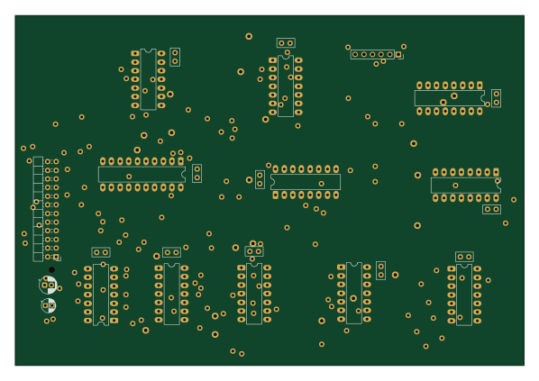
Flags
149.4 × 102.8 mm26 parts2LNo license8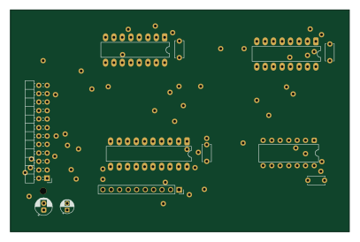
Sp register
101.5 × 66.5 mm12 parts2LNo license8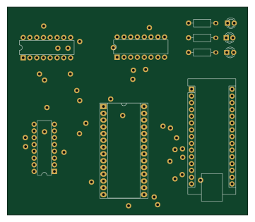 AVR/Arduino
AT28C64B-circuit second sol
90 × 78 mm11 parts2LNo license8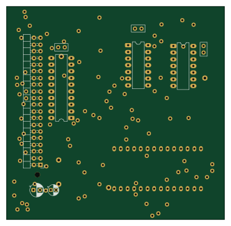
Ram
82.8 × 81 mm11 parts2LNo license8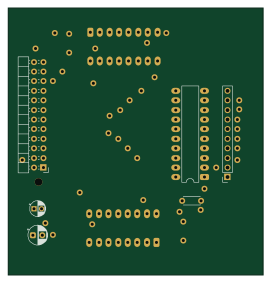
Register
67.5 × 70.6 mm10 parts2LNo license8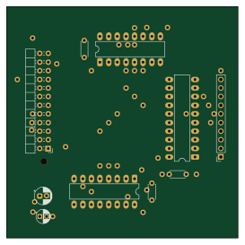
Sh register
68 × 68 mm10 parts2LNo license8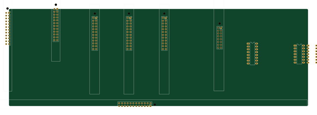
V1
266.6 × 86.9 mm10 parts2LNo license8