
Red light panel

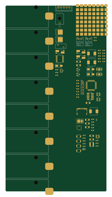
About the Red light panel PCB
Red light panel is an open source STM32 PCB design by Lucas-Poulos, published on GitHub under the CERN-OHL-P-2.0 license. It is a 2-layer board measuring 91.5 × 168.5 mm, with 153 components from 48 distinct parts.
Its main chip is the STM32G031K8T6, from the STM32 family. Other key parts include the BQ7692000PWR, TPS25751DREFR, BQ25792RQMR, TPS563201DDCR and LM3409HVMY/NOPB. By type, the board carries 71 diodes, 24 capacitors, 21 resistors, 8 battery holders, 7 ICs and 7 connectors.
It belongs with the power & battery designs in this gallery.
From the project
Battery-powered 660nm red light therapy panel — KiCad 10 hardware project
A battery-powered 660nm red light therapy panel. 4S2P 18650 Li-ion pack (~74Wh-class), USB-C PD charging, ~74W LED load across two independently PWM-dimmable channels, STM32-based control with a 4-button HMI.
KiCad 10 hardware project — schematic + BOM. PCB placement/routing is out of scope for this pass, but the board is fab-ready to route against: 2-layer, 1oz/1oz copper, JLCPCB-standard-service design rules with margin (not run at the fabrication limit) — see docs/pcbfabricationrules.md for the exact values and rationale. All 153 components are imported onto the board from the schematic.
Main components on the Red light panel
Red light panel bill of materials (BOM)
153 components, 48 distinct parts — part numbers from the project's BOM.
| Qty | Part | Footprint | Refs |
|---|---|---|---|
| 1 | BQ7692000PWR BQ76920PW Texas Instruments | TSSOP-20_4.4x6.5mm_P0.65mm | U1 |
| 1 | TPS25751DREFR TPS25751DREFR (active replacement for NRND TPS25750DRYR, per your decision) Texas Instruments | Texas_REF0038A_WQFN-38-2EP_6x4mm_P0.4 | U2 |
| 1 | BQ25792RQMR Texas Instruments | Texas_RQM0029A_VQFN-29_4x4mm_P0.4mm | U3 |
| 1 | TPS563201DDCR Texas Instruments | SOT-23-6 | U4 |
| 2 | LM3409HVMY/NOPB Texas Instruments | HVSSOP-10-1EP_3x3mm_P0.5mm_EP1.83x1.89mm | U5, U6 |
| 1 | STM32G031K8T6 STMicroelectronics | LQFP-32_7x7mm_P0.8mm | U7 |
| 2 | CSD18540Q5B Texas Instruments | TDSON-8-1 | Q1, Q2 |
| 1 | AO3401A Alpha & Omega Semiconductor | SOT-23 | Q3 |
| 2 | AO3401A AO3401A (30V Vds, satisfies brief's margin flag) Alpha & Omega Semiconductor | SOT-23 | Q4, Q5 |
| 1 | B5B-XH-A JST B5B-XH-A JST | JST_XH_B5B-XH-A_1x05_P2.50mm_Vertical | J1 |
| 1 | 43045-0200 Molex 43045-0200 Molex | Molex_Micro-Fit_3.0_43045-0200_2x01_P3.00mm_Horizontal | J2 |
| 1 | USB4105-GF-A USB4105-GF-A (plating/stake length TBD, flag) GCT | USB_C_Receptacle_GCT_USB4105-xx-A_16P_TopMnt_Horizontal | J3 |
| 2 | B2B-PH-K-S(LF)(SN) 2-pin screw terminal / JST-PH-2 JST | JST_PH_S2B-PH-K_1x02_P2.00mm_Horizontal | J4, J5 |
| 1 | FTSH-105-01-F-DV-K (footprint substituted, flag) Cortex Debug 10-pin Samtec | PinHeader_2x05_P1.27mm_Vertical_SMD | J6 |
| 1 | PREC005SAAN-RC Debug breakout (SWDIO,SWCLK,NRST,3.3V,GND) Sullins | PinHeader_1x05_P2.54mm_Vertical | J7 |
| 8 | Samsung INR18650-30Q INR18650-30Q Samsung SDI | BatteryHolder_Keystone_1042_1x18650 | BT1, BT2, BT3, BT4, BT5, BT6, BT7, BT8 |
| 1 | 0ZRE0025FF (corrected from placeholder MICROSMD250F/16-2 -- FLAG FOR REVIEW) 0.25A resettable Bel Fuse | Fuse_BelFuse_0ZRE0025FF_L9.6mm_W3.8mm | F1 |
| 1 | NCP18XH103F03RB NCP18XH103F03RB (10k NTC) Murata | R_0603_1608Metric | RT1 |
| 4 | B3U-1000P Omron B3U-1000P Omron | SW_SPST_B3U-1000P | SW1, SW2, SW3, SW4 |
| 1 | SMAJ24CA Littelfuse | D_SMA | D1 |
Show 28 more
| Qty | Part | Footprint | Refs |
|---|---|---|---|
| 1 | TPD4S012DRYR TPD4S012DRYR (corrected from BOM's TPD4S012DBVR -- flag) Texas Instruments | Texas_USON-6_1x1.45mm_P0.5mm_SMD | D2 |
| 2 | SS54 onsemi/Diodes Inc (generic SS54) | D_SMA | D3, D4 |
| 64 | SST-10-DR-B130-K660 Luminus Devices | LUMINUS_SST-10-3535 | D5, D6, D7, D8, D9, D10, D11, D12 +56 |
| 2 | TPD4E001DBVR TPD4E001DBVR (corrected from BOM's TPD4E001DZDR -- flag) Texas Instruments | SOT-23-6 | D69, D70 |
| 1 | APT1608LSECK/J4-PRV APT1608LSECK/J4-PRV (single-color, corrected per your decision) Kingbright | LED_0603_1608Metric | D71 |
| 1 | 744031220 2.2uH (Wurth 744031220) Wurth Elektronik | L_Vishay_IFSC-1515AH_4x4x1.8mm | L1 |
| 2 | IHLP2525CZERR10M01 IHLP2525CZERR10M01 (0.10uH) Vishay Dale | L_Vishay_IHLP-2525 | L2, L3 |
| 1 | 2.2uH (added, flagged -- calc vs target charge current) | L_Vishay_IHLP-2525 | L90 |
| 5 | CC1206KKX7R8BB106 10uF Yageo | C_1206_3216Metric | C1, C2, C6, C12, C13 |
| 11 | CC0603KRX7R9BB104 0.1uF Yageo | C_0603_1608Metric | C3, C4, C5, C8, C9, C10, C11, C14 +3 |
| 1 | CC1206KKX5R7BB106 10uF Yageo | C_1206_3216Metric | C7 |
| 1 | CC1206KKX7R8BB475 4.7uF Yageo | C_1206_3216Metric | C18 |
| 1 | 1uF (added, flagged) | C_0603_1608Metric | C90 |
| 1 | 0.1uF (added, flagged) | C_0603_1608Metric | C91 |
| 1 | 1uF (added, flagged -- PMID bulk cap per typical app circuit) | C_1206_3216Metric | C92 |
| 1 | 2.2nF (added, flagged -- VBST bootstrap cap) | C_0603_1608Metric | C93 |
| 2 | 100pF (added, flagged -- COFF timing, calc vs L freq) | C_0603_1608Metric | C94, C95 |
| 1 | WSL2512R0100FEA 0.01R 1% Vishay Dale | R_Shunt_Vishay_WSK2512_6332Metric_T2.21mm | R1 |
| 8 | RC0603FR-0710KL 10k Yageo | R_0603_1608Metric | R2, R6, R7, R8, R9, R10, R11, R12 |
| 1 | RC0603FR-073K01L 3.01k (calc, flag) Yageo | R_0603_1608Metric | R3 |
| 2 | WSL2512R0200FEA 0.02R 1% Vishay Dale | R_Shunt_Vishay_WSK2512_6332Metric_T2.21mm | R4, R5 |
| 1 | RC0603FR-07680RL 680R (calc vs Vf/If, flag) Yageo | R_0603_1608Metric | R13 |
| 1 | RC0603FR-07100KL 100k Yageo | R_0603_1608Metric | R90 |
| 1 | 10k (added, flagged -- ILIM_HIZ set resistor, calc per datasheet eqn) | R_0603_1608Metric | R91 |
| 1 | 4.7k (added, flagged -- PROG set resistor, calc per datasheet eqn) | R_0603_1608Metric | R92 |
| 2 | 100k (added, flagged -- COFF timing, calc vs L freq) | R_0603_1608Metric | R94, R96 |
| 2 | 100k (added, flagged -- UVLO always-on pull-up, no set threshold) | R_0603_1608Metric | R95, R97 |
| 1 | 10k (added, flagged -- NTC divider pull-up) | R_0603_1608Metric | R98 |
Red light panel design files
The KiCad project lives in the Lucas-Poulos/red-light-panel repository on GitHub; these links point at the commit this page was built from.
Red light panel: common questions
What microcontroller does the Red light panel use?
The Red light panel is built around the STM32G031K8T6, from the STM32 family.
How big is the Red light panel PCB?
The Red light panel measures 91.5 × 168.5 mm, has 2 copper layers and is 1.6 mm thick.
How many components are on the Red light panel?
153 components, from 48 distinct parts, with part numbers taken from the project's own BOM. The full bill of materials is listed on this page.
Where can I download the Red light panel design files?
From the Lucas-Poulos/red-light-panel repository on GitHub, which has the KiCad layout, the schematic and the BOM; the links under Design files point to each one.
Can I use the Red light panel design in my own project?
Yes, under the terms of its CERN-OHL-P-2.0 license, which Lucas-Poulos chose for the repository.
Can I test firmware for the Red light panel without the hardware?
Yes. HardLabs builds a simulation of the board from its netlist and BOM, so you can run and debug STM32 firmware against it before you order a PCB.
Similar boards
 STM32
STM32LumenPnP Motherboard
opulo-inc
149 × 95 mm296 parts4LCC-BY-SA-4.03.7k STM32
STM32AxxSolder
AxxAxx
39 × 82.5 mm122 parts2LGPL-3.01.7k STM32
STM32AIOC
skuep
21 × 31.5 mm47 parts2LMIT1.4k STM32
STM32Ferris
pierrechevalier83
208.8 × 86.8 mm102 parts2LSHL-2.11.3k STM32
STM32Module 16S
stuartpittaway
71.1 × 89.6 mm113 parts4LCC-BY-NC-4.01.1k STM32
STM32Djinn
tzarc
192.3 × 150.5 mm216 parts2LCERN-OHL-S-2.0988