
SX1255

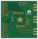
About the SX1255 PCB
SX1255 is an open source PCB design by M17-Project, published on GitHub under the CC-BY-NC-4.0 license. It is a 2-layer board measuring 40 × 41 mm, with 30 components from 13 distinct parts.
Other key parts include the 947-SX1255IWLTRT. By type, the board carries 12 capacitors, 9 resistors, 5 connectors, 2 inductors, 1 IC and 1 jumper.
It belongs with the dev boards & breakouts and rf & radio designs in this gallery.
From the project
Evaluation board for the SX1255 RF transceiver chip
Sample Raspberry Pi code for SX1255 control can be found here. I2S slave overlay is required.
[cc-by-nc-sa]: http://creativecommons.org/licenses/by-nc-sa/4.0/ [cc-by-nc-sa-image]: https://licensebuttons.net/l/by-nc-sa/4.0/88x31.png [cc-by-nc-sa-shield]: https://img.shields.io/badge/License-CC%20BY--NC--SA%204.0-lightgrey.svg
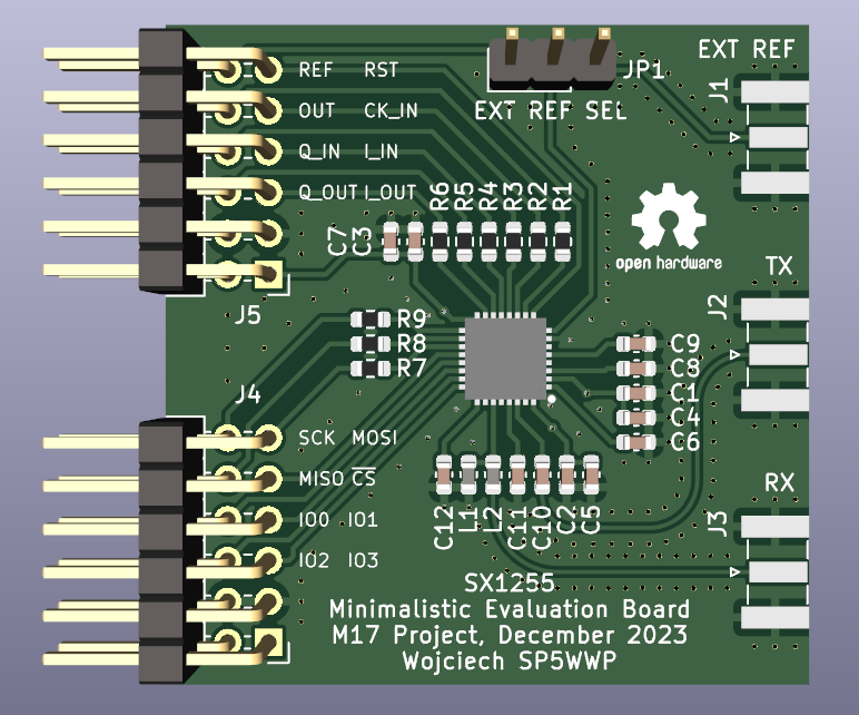
Main components on the SX1255
SX1255 bill of materials (BOM)
30 components, 13 distinct parts — part numbers from the project's BOM.
| Qty | Part | Footprint | Refs |
|---|---|---|---|
| 1 | 947-SX1255IWLTRT SX1255 | QFN50P500X500X80-33N-D | IC1 |
| 1 | - EXT_CLK_IN | SMA_Samtec_SMA-J-P-X-ST-EM1_EdgeMount | J1 |
| 1 | - TX_SMA | SMA_Samtec_SMA-J-P-X-ST-EM1_EdgeMount | J2 |
| 1 | - RX_SMA | SMA_Samtec_SMA-J-P-X-ST-EM1_EdgeMount | J3 |
| 2 | PMOD | PinHeader_2x06_P2.54mm_Horizontal | J4, J5 |
| 1 | EXT_CLK_SRC | PinHeader_1x03_P2.54mm_Vertical | JP1 |
| 1 | 82N 82n | L_0603_1608Metric | L1 |
| 1 | 39N 39n | L_0603_1608Metric | L2 |
| 3 | C0603C103K5RAC7081 10n | C_0603_1608Metric | C1, C2, C3 |
| 7 | C0603C104M5RAC7411 100n | C_0603_1608Metric | C4, C5, C6, C7, C8, C9, C12 |
| 1 | 33P 33p | C_0603_1608Metric | C10 |
| 1 | 27P 27p | C_0603_1608Metric | C11 |
| 9 | CRCW0603100RFKECC 100R | R_0603_1608Metric | R1, R2, R3, R4, R5, R6, R7, R8 +1 |
SX1255 design files
The KiCad project lives in the M17-Project/SX1255 repository on GitHub; these links point at the commit this page was built from.
- Layoutsx1255_eval.kicad_pcb
- Schematicsx1255_eval.kicad_sch
- BOMsx1255_bom.csv
SX1255: common questions
How big is the SX1255 PCB?
The SX1255 measures 40 × 41 mm, has 2 copper layers and is 1.6 mm thick.
How many components are on the SX1255?
30 components, from 13 distinct parts, with part numbers taken from the project's own BOM. The full bill of materials is listed on this page.
Where can I download the SX1255 design files?
From the M17-Project/SX1255 repository on GitHub, which has the KiCad layout, the schematic and the BOM; the links under Design files point to each one.
Can I use the SX1255 design in my own project?
It is published under CC-BY-NC-4.0, which limits how it may be reused; read the license before building on it.
Similar boards
134pin 7-967288-1
rusefi
139.7 × 73.7 mm38 parts2LGPL-3.01.2k
Breakout 112pin Connector
174 × 58 mm39 parts2LGPL-3.01.2k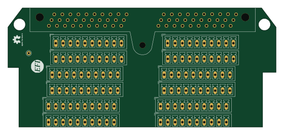
Breakout 60pin EEC-IV
139.7 × 62.2 mm15 parts2LGPL-3.01.2k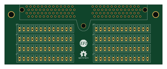
Eecv breakout
140.8 × 53.7 mm9 parts4LGPL-3.01.2k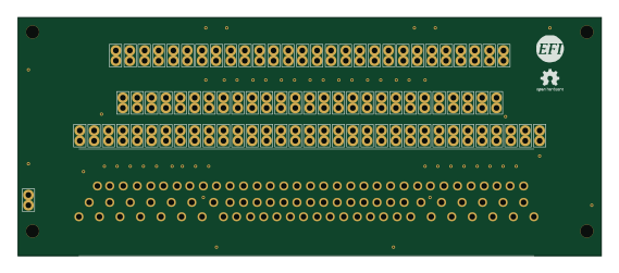
88 Pin Vag Breakout
142 × 58 mm91 parts2LGPL-3.01.2k
Rj45 breakout
rene-dev
15.2 × 53.8 mm3 parts2LGPL-3.0979