
Raspberry Pi 5 PCIe Breakout

About the Raspberry Pi 5 PCIe Breakout
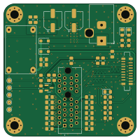
Raspberry Pi 5 PCIe Breakout is an open source PCB design by m1geo, published on GitHub under the MIT license. It is a 4-layer board measuring 50 × 50 mm, with 45 components from 17 distinct parts.
Other key parts include the Mini360. By type, the board carries 20 capacitors, 15 resistors, 5 diodes, 3 connectors, 1 IC and 1 transistor.
It belongs with the dev boards & breakouts designs in this gallery.
From the project
A crude reverse engineering of the Pi5 PCIe connector & potential breakout boards.
OFFICIAL RASPBERRY PI PCIE DOCOUMENTATION CAN BE FOUND HERE: https://datasheets.raspberrypi.com/pcie/pcie-connector-standard.pdf
In this bare-bones project I document a working PCIe pinout talk through my hardware tinkering to get the Raspberry Pi 5's PCIe connected to something. I had only seen Raspberry Pi's boards with their RP2040 and lots of parts on board. My professional experience with PCIe was that it either just goes or it really doesn't. I decided to try and make it do something for no reason other than the technical challenge.
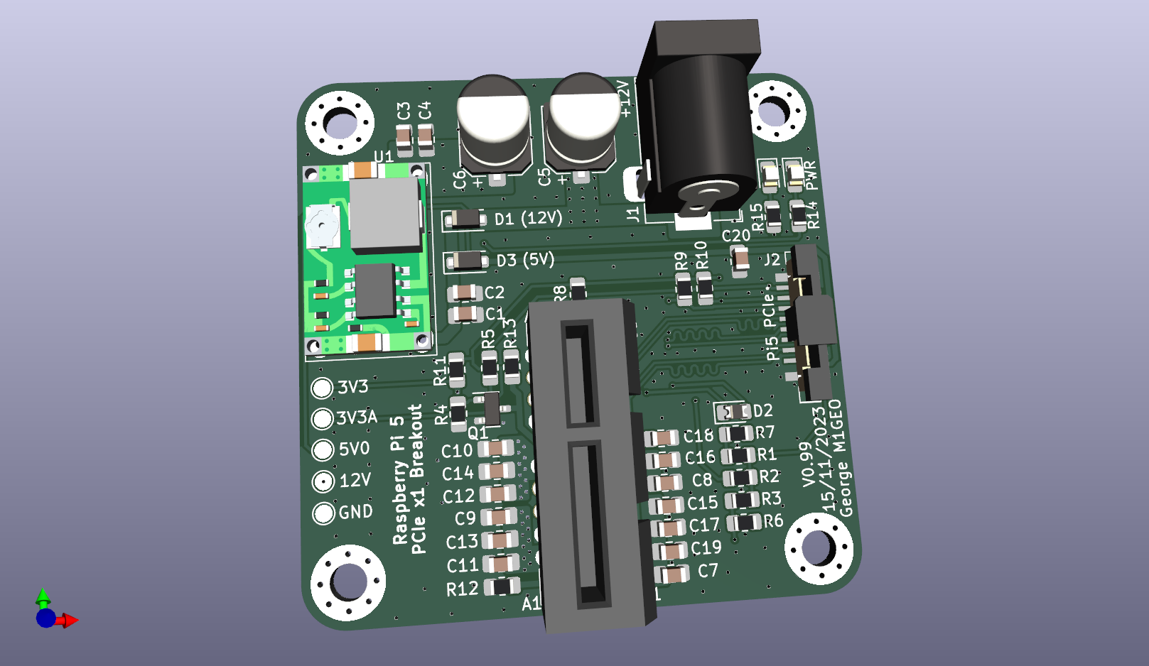
Main components on the Raspberry Pi 5 PCIe Breakout
Raspberry Pi 5 PCIe Breakout bill of materials (BOM)
45 components, 17 distinct parts.
| Qty | Part | Footprint | Refs |
|---|---|---|---|
| 1 | Mini360 | Mini360_step-down | U1 |
| 1 | BS170F | SOT-23 | Q1 |
| 1 | 12V IN | BarrelJack_Horizontal | J1 |
| 1 | Wurth 687316124422 Pi5 PCIe | 687316124422 | J2 |
| 1 | 10018783-11200TLF | AMPHENOL_10018783-11200TLF | J3 |
| 1 | (12V) | D_SOD-123F | D1 |
| 1 | DNF | D_0805_2012Metric_Pad1.15x1.40mm_HandSolder | D2 |
| 1 | (5V) | D_SOD-123F | D3 |
| 1 | PWR | LED_0805_2012Metric_Pad1.15x1.40mm_HandSolder | D4 |
| 1 | RST | LED_0805_2012Metric_Pad1.15x1.40mm_HandSolder | D5 |
| 12 | 100n | C_0805_2012Metric_Pad1.18x1.45mm_HandSolder | C1, C3, C11, C12, C13, C14, C15, C16 +4 |
| 6 | 10u | C_0805_2012Metric_Pad1.18x1.45mm_HandSolder | C2, C4, C7, C8, C9, C10 |
| 2 | 150u | CP_Elec_6.3x7.7 | C5, C6 |
| 3 | DNF | R_0805_2012Metric_Pad1.20x1.40mm_HandSolder | R1, R2, R3 |
| 7 | 10k | R_0805_2012Metric_Pad1.20x1.40mm_HandSolder | R4, R6, R7, R8, R9, R10, R13 |
| 3 | 0 | R_0805_2012Metric_Pad1.20x1.40mm_HandSolder | R5, R11, R12 |
| 2 | 1k | R_0805_2012Metric_Pad1.20x1.40mm_HandSolder | R14, R15 |
Raspberry Pi 5 PCIe Breakout design files
The KiCad project lives in the m1geo/Pi5_PCIe repository on GitHub; these links point at the commit this page was built from.
- LayoutPi5_PCIe.kicad_pcb
- SchematicPi5_PCIe.kicad_sch
Raspberry Pi 5 PCIe Breakout: common questions
How big is the Raspberry Pi 5 PCIe Breakout?
The Raspberry Pi 5 PCIe Breakout measures 50 × 50 mm, has 4 copper layers and is 1.6162 mm thick.
How many components are on the Raspberry Pi 5 PCIe Breakout?
45 components, from 17 distinct parts. The full bill of materials is listed on this page.
Where can I download the Raspberry Pi 5 PCIe Breakout design files?
From the m1geo/Pi5_PCIe repository on GitHub, which has the KiCad layout and the schematic; the links under Design files point to each one.
Can I use the Raspberry Pi 5 PCIe Breakout design in my own project?
Yes, under the terms of its MIT license, which m1geo chose for the repository.
More boards in Pi5_PCIe
Similar boards
88 Pin Vag Breakout
rusefi
142 × 58 mm91 parts2LGPL-3.01.2k
134pin 7-967288-1
139.7 × 73.7 mm38 parts2LGPL-3.01.2k
Breakout 60pin EEC-IV
139.7 × 62.2 mm15 parts2LGPL-3.01.2k
Breakout 112pin Connector
174 × 58 mm39 parts2LGPL-3.01.2k
Eecv breakout
140.8 × 53.7 mm9 parts4LGPL-3.01.2k
Rj45 breakout
rene-dev
15.2 × 53.8 mm3 parts2LGPL-3.0979