
M2-IO-Emulator-Board

About the M2-IO-Emulator-Board
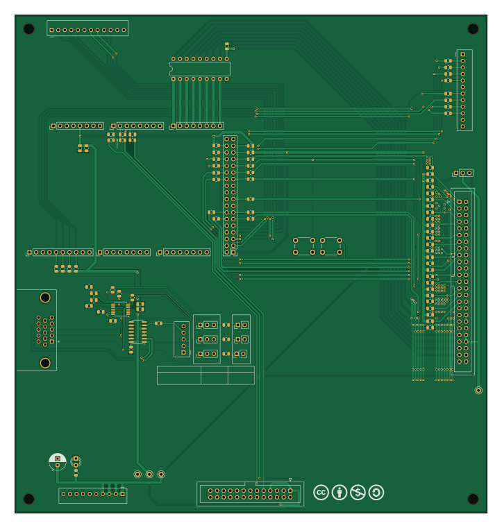
M2-IO-Emulator-Board is an open source PCB design by Maillouski, published on GitHub under the CC-BY-NC-4.0 license. It is a 2-layer board measuring 180 × 190 mm, with 112 components from 28 distinct parts.
Other key parts include the ULN2803A, 74HCT86D,653 and OPA3355EA/2K5. By type, the board carries 59 resistors, 23 capacitors, 13 connectors, 7 jumpers, 4 test points and 3 ICs.
It belongs with the retro computing designs in this gallery.
From the project
Drop-in replacement for the Sega 837-10539 I/O board (Daytona USA twin, Model 2), built around an Arduino Mega 2560. KiCad 10, CC BY-NC-SA 4.0.
A drop-in replacement for the Sega 837-10539 I/O board of the Daytona USA twin cabinet (Sega Model 2), built around an Arduino Mega 2560. It lets an emulator drive the original cabinet: controls, lamps, meters, the original drive board (force feedback) and the original arcade monitor.
The idea is simple: pull the Sega I/O board out of the cabinet and put this one in its place. It has the same size, the same mounting holes and the same connector names, so the original harness plugs straight in. Nothing gets cut or rewired.
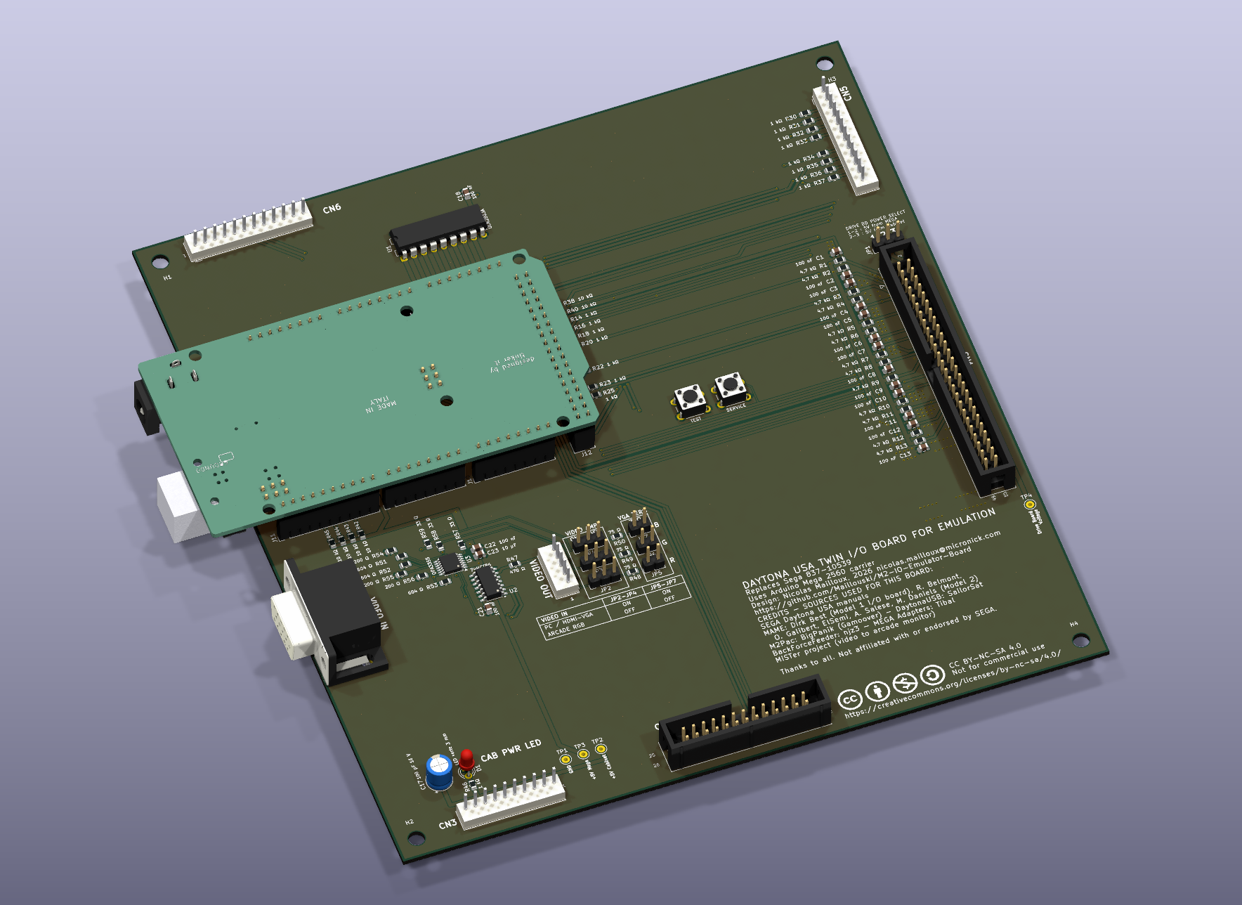
Main components on the M2-IO-Emulator-Board
M2-IO-Emulator-Board bill of materials (BOM)
112 components, 28 distinct parts — part numbers from the project's BOM.
| Qty | Part | Footprint | Refs |
|---|---|---|---|
| 1 | ULN2803A | DIP-18_W7.62mm | U1 |
| 1 | 74HCT86D,653 74HCT86 | SOIC-14_3.9x8.7mm_P1.27mm | U2 |
| 1 | OPA3355EA/2K5 OPA3355EA | TSSOP-14_4.4x5mm_P0.65mm | U3 |
| 1 | N2550-6002-RB | IDC-Header_2x25_P2.54mm_Vertical | J1 |
| 1 | N2526-6002-RB | IDC-Header_2x13_P2.54mm_Vertical | J2 |
| 1 | B10P-SHF-1AA | JST_NH_B10P-SHF-1AA_1x10_P2.50mm_Vertical | J3 |
| 2 | B12P-SHF-1AA | JST_NH_B12P-SHF-1AA_1x12_P2.50mm_Vertical | J4, J5 |
| 5 | 61300811121 | PinHeader_1x08_P2.54mm_Vertical | J6, J7, J8, J9, J10 |
| 1 | 61301011121 | PinHeader_1x10_P2.54mm_Vertical | J11 |
| 1 | Pin Header 02x18 2.54mm Vertical | PinHeader_2x18_P2.54mm_Vertical | J12 |
| 1 | B5P-SHF-1AA VIDEO | JST_NH_B5P-SHF-1AA_1x05_P2.50mm_Vertical | J14 |
| 4 | 61300311121 | PinHeader_1x03_P2.54mm_Vertical | JP1, JP2, JP3, JP4 |
| 3 | 61300211121 | PinHeader_1x02_P2.54mm_Vertical | JP5, JP6, JP7 |
| 1 | 1825910-6 TEST | SW_PUSH_6mm | SW1 |
| 1 | 1825910-6 SERVICE | SW_PUSH_6mm | SW2 |
| 4 | 5002 | TestPoint_Keystone_5000-5004_Miniature | TP1, TP2, TP3, TP4 |
| 1 | LED verte 3 mm | LED_D3.0mm | D1 |
| 20 | CC0805KRX7R9BB104 100 nF | C_0805_2012Metric | C1, C2, C3, C4, C5, C6, C7, C8 +12 |
| 1 | EEU-FC1C101 100 µF 16 V | CP_Radial_D6.3mm_P2.50mm | C17 |
| 2 | CL21B106KOQNNNG 10 µF | C_0805_2012Metric | C19, C23 |
Show 8 more
| Qty | Part | Footprint | Refs |
|---|---|---|---|
| 13 | RC0805FR-074K7L 4,7 kΩ | R_0805_2012Metric | R1, R2, R3, R4, R5, R6, R7, R8 +5 |
| 25 | RC0805FR-071KL 1 kΩ | R_0805_2012Metric | R14, R15, R16, R17, R18, R19, R20, R21 +17 |
| 8 | RC0805FR-0710KL 10 kΩ | R_0805_2012Metric | R38, R39, R40, R41, R42, R43, R44, R45 |
| 1 | RC0805FR-07470RL 470 Ω | R_0805_2012Metric | R47 |
| 3 | RC0805FR-0775RL 75 Ω | R_0805_2012Metric | R48, R49, R50 |
| 3 | RC0805FR-07604RL 604 Ω | R_0805_2012Metric | R51, R52, R53 |
| 3 | RC0805FR-07200RL 200 Ω | R_0805_2012Metric | R54, R55, R56 |
| 3 | RC0805FR-0733RL 33 Ω | R_0805_2012Metric | R57, R58, R59 |
M2-IO-Emulator-Board design files
The KiCad project lives in the Maillouski/M2-IO-Emulator-Board repository on GitHub; these links point at the commit this page was built from.
M2-IO-Emulator-Board: common questions
How big is the M2-IO-Emulator-Board?
The M2-IO-Emulator-Board measures 180 × 190 mm, has 2 copper layers and is 1.4986 mm thick.
How many components are on the M2-IO-Emulator-Board?
112 components, from 28 distinct parts, with part numbers taken from the project's own BOM. The full bill of materials is listed on this page.
Where can I download the M2-IO-Emulator-Board design files?
From the Maillouski/M2-IO-Emulator-Board repository on GitHub, which has the KiCad layout, the schematic and the BOM; the links under Design files point to each one.
Can I use the M2-IO-Emulator-Board design in my own project?
It is published under CC-BY-NC-4.0, which limits how it may be reused; read the license before building on it.
Similar boards
Expansion Card Retrofit
FrameworkComputer
24 × 27.3 mm5 parts2LCC-BY-4.01.1k
Rgb to hdmi
hoglet67
77 × 97 mm67 parts2LGPL-3.01.0k
Buffer
53.9 × 23.2 mm13 parts2LGPL-3.01.0k
X1
121.9 × 81.3 mm51 parts2LGPL-3.01.0k
Amiga External
21.9 × 76.7 mm6 parts2LGPL-3.01.0k
Videoslotadapter
152 × 57.6 mm13 parts2LGPL-3.01.0k