
TAILS

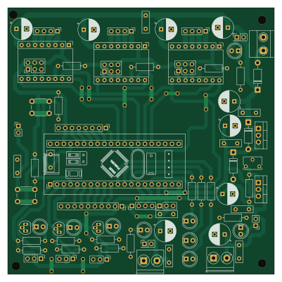
About the TAILS PCB
TAILS is an open source STM32 PCB design by Mario-dango, published on GitHub. It is a 2-layer board measuring 100 × 100 mm, with 80 components from 49 distinct parts.
Its main chip is the YAAJ_BluePill, from the STM32 family. Other key parts include the LM7805_TO220, LM317_TO-220 and Pololu_Breakout_A4988. By type, the board carries 20 connectors, 18 capacitors, 18 resistors, 12 diodes, 3 ICs and 3 modules.
It belongs with the robotics & motion designs in this gallery.
From the project
T.A.I.L.S. - Ecosistema de control para brazo robótico (3-DOF + Gripper). Incluye Interfaz Gráfica en Python (PyQt5), Firmware C/C++ (STM32 HAL) y diseño de PCB.
Este directorio contiene todo el proyecto de diseño de hardware (Hardware Design) de la placa de control principal para el brazo robótico T.A.I.L.S.
El diseño fue realizado íntegramente en KiCad, buscando crear un placa base robusta que elimine el cableado protoboard, minimice el ruido eléctrico y centralice el control de potencia y señales.
El cerebro de la placa es un microcontrolador STM32F103C8T6 (Bluepill). El circuito está dividido en bloques funcionales para facilitar su análisis y mantenimiento:
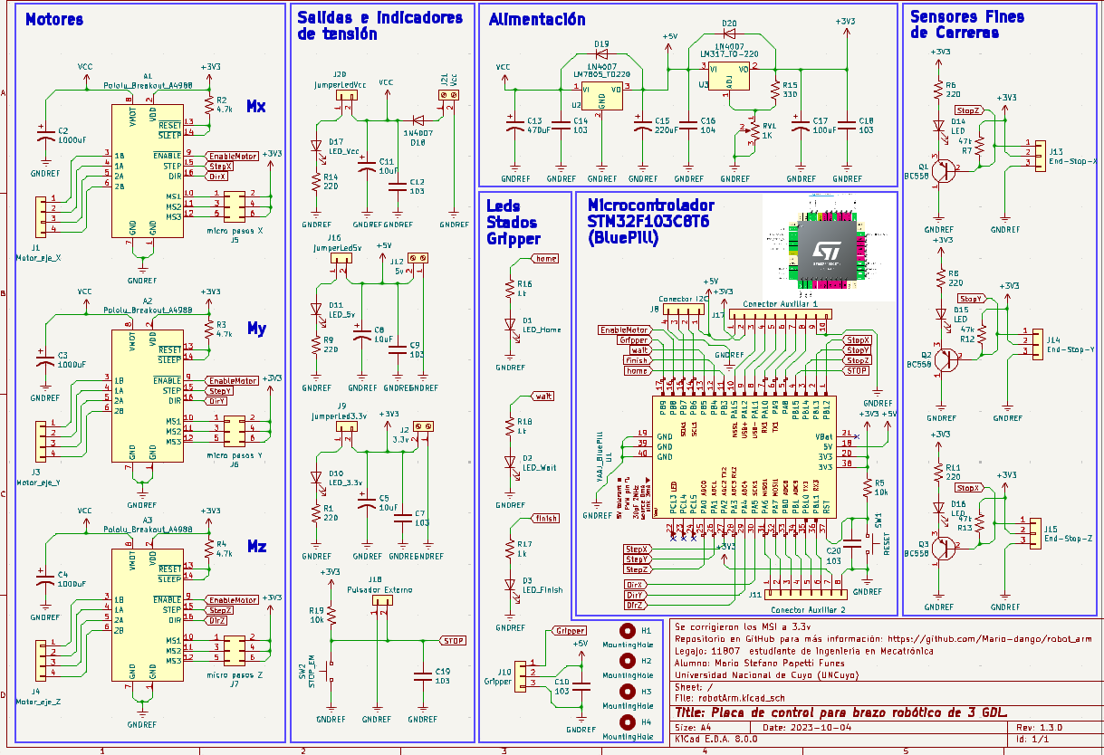
Main components on the TAILS
TAILS bill of materials (BOM)
80 components, 49 distinct parts.
| Qty | Part | Footprint | Refs |
|---|---|---|---|
| 1 | YAAJ_BluePill | YAAJ_BluePill_1 | U1 |
| 1 | LM7805_TO220 | TO-220-3_Vertical | U2 |
| 1 | LM317_TO-220 | TO-220-3_Vertical | U3 |
| 3 | Pololu_Breakout_A4988 | Pololu_Breakout-16_15.2x20.3mm | A1, A2, A3 |
| 3 | BC558 | TO-92_HandSolder | Q1, Q2, Q3 |
| 1 | Motor_eje_X | PinHeader_1x04_P2.54mm_Vertical | J1 |
| 1 | 3.3v | TerminalBlock_Phoenix_PT-1,5-2-5.0-H_1x02_P5.00mm_Horizontal | J2 |
| 1 | Motor_eje_Y | PinHeader_1x04_P2.54mm_Vertical | J3 |
| 1 | Motor_eje_Z | PinHeader_1x04_P2.54mm_Vertical | J4 |
| 1 | micro pasos X | PinHeader_2x03_P2.54mm_Vertical | J5 |
| 1 | micro pasos Y | PinHeader_2x03_P2.54mm_Vertical | J6 |
| 1 | micro pasos Z | PinHeader_2x03_P2.54mm_Vertical | J7 |
| 1 | Conector I2C | PinHeader_1x04_P2.54mm_Vertical | J8 |
| 1 | jumperLed3.3v | PinHeader_1x02_P2.54mm_Vertical | J9 |
| 1 | Gripper | PinHeader_1x03_P2.54mm_Vertical | J10 |
| 1 | Conector Auxiliar 2 | PinHeader_1x08_P2.54mm_Vertical | J11 |
| 1 | 5v | TerminalBlock_Phoenix_PT-1,5-2-5.0-H_1x02_P5.00mm_Horizontal | J12 |
| 1 | End-Stop-X | PinHeader_1x03_P2.54mm_Vertical | J13 |
| 1 | End-Stop-Y | PinHeader_1x03_P2.54mm_Vertical | J14 |
| 1 | End-Stop-Z | PinHeader_1x03_P2.54mm_Vertical | J15 |
Show 29 more
| Qty | Part | Footprint | Refs |
|---|---|---|---|
| 1 | jumperLed5v | PinHeader_2x01_P2.54mm_Vertical | J16 |
| 1 | Conector Auxiliar 1 | PinSocket_1x10_P2.54mm_Vertical | J17 |
| 1 | Pulsador Externo | PinHeader_1x02_P2.54mm_Vertical | J18 |
| 1 | jumperLedVcc | PinHeader_2x01_P2.54mm_Vertical | J20 |
| 1 | Vcc | TerminalBlock_Phoenix_MKDS-1,5-2_1x02_P5.00mm_Horizontal | J21 |
| 1 | 1K | Potentiometer_Bourns_3266W_Vertical | RV1 |
| 1 | RESET | SW_PUSH_6mm_H5mm | SW1 |
| 1 | STOP_EM | SW_PUSH_6mm_H5mm | SW2 |
| 1 | LED_Home | LED_D5.0mm | D1 |
| 1 | LED_Wait | LED_D5.0mm | D2 |
| 1 | LED_Finish | LED_D5.0mm | D3 |
| 1 | LED_3.3v | LED_D5.0mm | D10 |
| 1 | LED_5v | LED_D5.0mm | D11 |
| 3 | LED | LED_D5.0mm | D14, D15, D16 |
| 1 | LED_Vcc | LED_D5.0mm | D17 |
| 3 | 1N4007 | D_DO-41_SOD81_P10.16mm_Horizontal | D18, D19, D20 |
| 3 | 1000uF | CP_Radial_D8.0mm_P3.80mm | C2, C3, C4 |
| 3 | 10uF | CP_Radial_D8.0mm_P3.80mm | C5, C8, C11 |
| 8 | 103 | C_Disc_D8.0mm_W2.5mm_P5.00mm | C7, C9, C10, C12, C14, C18, C19, C20 |
| 1 | 470uF | CP_Radial_D8.0mm_P3.80mm | C13 |
| 1 | 220uF | CP_Radial_D8.0mm_P3.80mm | C15 |
| 1 | 104 | C_Disc_D8.0mm_W2.5mm_P5.00mm | C16 |
| 1 | 100uF | CP_Radial_D8.0mm_P3.80mm | C17 |
| 6 | 220 | R_Axial_DIN0207_L6.3mm_D2.5mm_P10.16mm_Horizontal | R1, R6, R8, R9, R11, R14 |
| 3 | 4.7k | R_Axial_DIN0207_L6.3mm_D2.5mm_P10.16mm_Horizontal | R2, R3, R4 |
| 2 | 10k | R_Axial_DIN0207_L6.3mm_D2.5mm_P10.16mm_Horizontal | R5, R19 |
| 3 | 47k | R_Axial_DIN0207_L6.3mm_D2.5mm_P10.16mm_Horizontal | R7, R12, R13 |
| 1 | 330 | R_Axial_DIN0207_L6.3mm_D2.5mm_P10.16mm_Horizontal | R15 |
| 3 | 1k | R_Axial_DIN0207_L6.3mm_D2.5mm_P10.16mm_Horizontal | R16, R17, R18 |
TAILS design files
The KiCad project lives in the Mario-dango/TAILS repository on GitHub; these links point at the commit this page was built from.
- LayoutPCB/robotArm.kicad_pcb
- SchematicPCB/robotArm.kicad_sch
TAILS: common questions
What microcontroller does the TAILS use?
The TAILS is built around the YAAJ_BluePill, from the STM32 family.
How big is the TAILS PCB?
The TAILS measures 100 × 100 mm, has 2 copper layers and is 1.6 mm thick.
How many components are on the TAILS?
80 components, from 49 distinct parts. The full bill of materials is listed on this page.
Where can I download the TAILS design files?
From the Mario-dango/TAILS repository on GitHub, which has the KiCad layout and the schematic; the links under Design files point to each one.
Can I use the TAILS design in my own project?
The repository has no license, so all rights stay with Mario-dango. Use it as a reference, and ask the author before reusing the design.
Can I test firmware for the TAILS without the hardware?
Yes. HardLabs builds a simulation of the board from its netlist and BOM, so you can run and debug STM32 firmware against it before you order a PCB.
Similar boards
 STM32
STM32LumenPnP Motherboard
opulo-inc
149 × 95 mm296 parts4LCC-BY-SA-4.03.7k STM32
STM32AxxSolder
AxxAxx
39 × 82.5 mm122 parts2LGPL-3.01.7k STM32
STM32LibreVNA
jankae
122 × 98 mm592 parts6LGPL-3.01.6k STM32
STM32AIOC
skuep
21 × 31.5 mm47 parts2LMIT1.4k STM32
STM32Ferris
pierrechevalier83
208.8 × 86.8 mm102 parts2LSHL-2.11.3k STM32
STM32176 pin board
rusefi
61.8 × 73.2 mm76 parts2LGPL-3.01.2k