
CAN-Bus-Diagnostic-Adapter

About the CAN-Bus-Diagnostic-Adapter PCB
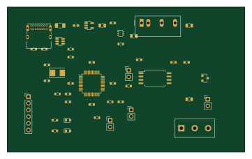
CAN-Bus-Diagnostic-Adapter is an open source STM32 PCB design by Matthew-Garcia, published on GitHub. It is a 2-layer board measuring 90 × 55 mm, with 47 components from 31 distinct parts.
Its main chip is the STM32F072CBT6, from the STM32 family. Other key parts include the AP2112K-3.3TRG1, ISO1042DUBR, TPS22919DCKR and TMR 1-0511. By type, the board carries 17 capacitors, 12 resistors, 5 ICs, 4 jumpers, 4 diodes and 3 connectors.
From the project
Custom USB-C CAN bus diagnostic PCB featuring STM32 control, isolated CAN communication, ESD protection, and selectable termination.
Designed for Matthew Garcia's USB-C / STM32 / isolated CAN diagnostic interface project.
Status: schematic and component-placement draft. The PCB has zero routed copper tracks. It is NOT ready to order or connect to a vehicle. Native KiCad ERC/DRC and physical testing have not been performed. No Gerbers or drill files are supplied because this is not a fabrication release.
Main components on the CAN-Bus-Diagnostic-Adapter
CAN-Bus-Diagnostic-Adapter bill of materials (BOM)
47 components, 31 distinct parts.
| Qty | Part | Footprint | Refs |
|---|---|---|---|
| 1 | STM32F072CBT6 | qfp | U1 |
| 1 | AP2112K-3.3TRG1 | sot235 | U2 |
| 1 | ISO1042DUBR | iso | U3 |
| 1 | TPS22919DCKR | sc706 | U4 |
| 1 | TMR 1-0511 | dcdc | U5 |
| 1 | ABM3-8.000MHZ-B2-T | crystal | Y1 |
| 1 | USB4085-GF-A | usb | J1 |
| 1 | CAN terminal 5.08mm | terminal | J2 |
| 1 | SWD 1x6 2.54mm | hdr6 | J3 |
| 1 | 1206L050YR 0.5A | fuse | F1 |
| 1 | RESET short to reset | hdr2 | JP1 |
| 1 | BOOT short for loader | hdr2 | JP2 |
| 1 | TX ENABLE normally OPEN | hdr2 | JP3 |
| 1 | 120R TERM normally OPEN | hdr2 | JP4 |
| 1 | USBLC6-2SC6 | sot236 | D1 |
| 1 | PESD2CAN | sot23 | D2 |
| 1 | GREEN LED | led | D3 |
| 1 | AMBER LED | led | D4 |
| 3 | 1uF 10V X7R | c0603 | C1, C3, C11 |
| 1 | 4.7uF 10V X7R | c0805 | C2 |
Show 11 more
| Qty | Part | Footprint | Refs |
|---|---|---|---|
| 2 | 4.7uF 16V X7R | c0805 | C4, C5 |
| 7 | 100nF 10V X7R | c0603 | C6, C7, C8, C9, C10, C14, C15 |
| 2 | 27pF C0G 50V | c0603 | C12, C13 |
| 1 | 100nF 16V X7R | c0603 | C16 |
| 1 | 1uF 16V X7R | c0603 | C17 |
| 2 | 5.1k 1% | r0603 | R1, R2 |
| 3 | 0R | r0603 | R3, R4, R6 |
| 1 | 100k | r0603 | R5 |
| 3 | 10k | r0603 | R7, R8, R11 |
| 2 | 1k | r0603 | R9, R10 |
| 1 | 120R 1% 0.25W | r0805 | R12 |
CAN-Bus-Diagnostic-Adapter design files
The KiCad project lives in the Matthew-Garcia/CAN-Bus-Diagnostic-Adapter repository on GitHub; these links point at the commit this page was built from.
- LayoutMG_CAN_RevA.kicad_pcb
CAN-Bus-Diagnostic-Adapter: common questions
What microcontroller does the CAN-Bus-Diagnostic-Adapter use?
The CAN-Bus-Diagnostic-Adapter is built around the STM32F072CBT6, from the STM32 family.
How big is the CAN-Bus-Diagnostic-Adapter PCB?
The CAN-Bus-Diagnostic-Adapter measures 90 × 55 mm, has 2 copper layers and is 1.6 mm thick.
How many components are on the CAN-Bus-Diagnostic-Adapter?
47 components, from 31 distinct parts. The full bill of materials is listed on this page.
Where can I download the CAN-Bus-Diagnostic-Adapter design files?
From the Matthew-Garcia/CAN-Bus-Diagnostic-Adapter repository on GitHub, which has the KiCad layout; the links under Design files point to each one.
Can I use the CAN-Bus-Diagnostic-Adapter design in my own project?
The repository has no license, so all rights stay with Matthew-Garcia. Use it as a reference, and ask the author before reusing the design.
Can I test firmware for the CAN-Bus-Diagnostic-Adapter without the hardware?
Yes. HardLabs builds a simulation of the board from its netlist and BOM, so you can run and debug STM32 firmware against it before you order a PCB.
Similar boards
 STM32
STM32LumenPnP Motherboard
opulo-inc
149 × 95 mm296 parts4LCC-BY-SA-4.03.7k STM32
STM32AxxSolder
AxxAxx
39 × 82.5 mm122 parts2LGPL-3.01.7k STM32
STM32LibreVNA
jankae
122 × 98 mm592 parts6LGPL-3.01.6k STM32
STM32AIOC
skuep
21 × 31.5 mm47 parts2LMIT1.4k STM32
STM32Ferris
pierrechevalier83
208.8 × 86.8 mm102 parts2LSHL-2.11.3k STM32
STM32176 pin board
rusefi
61.8 × 73.2 mm76 parts2LGPL-3.01.2k