
Goober

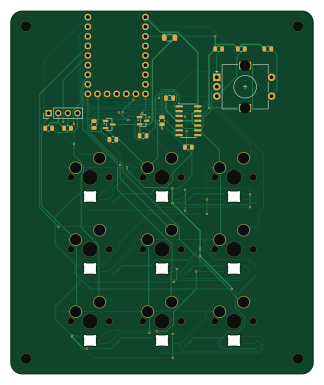
About the Goober PCB
Goober is an open source RP2040/RP2350 PCB design by maxthorson, published on GitHub. It is a 2-layer board measuring 80 × 96 mm, with 45 components from 16 distinct parts.
Its main chip is the Waveshare RP2040-Zero, from the RP2040/RP2350 family. Other key parts include the SN74AHCT125D. By type, the board carries 11 capacitors, 9 switches, 9 diodes, 9 resistors, 2 ICs and 2 transistors.
It belongs with the keyboards and wearables designs in this gallery.
From the project
the front page for the goober website, soon to have some cool keyboard. watch out!
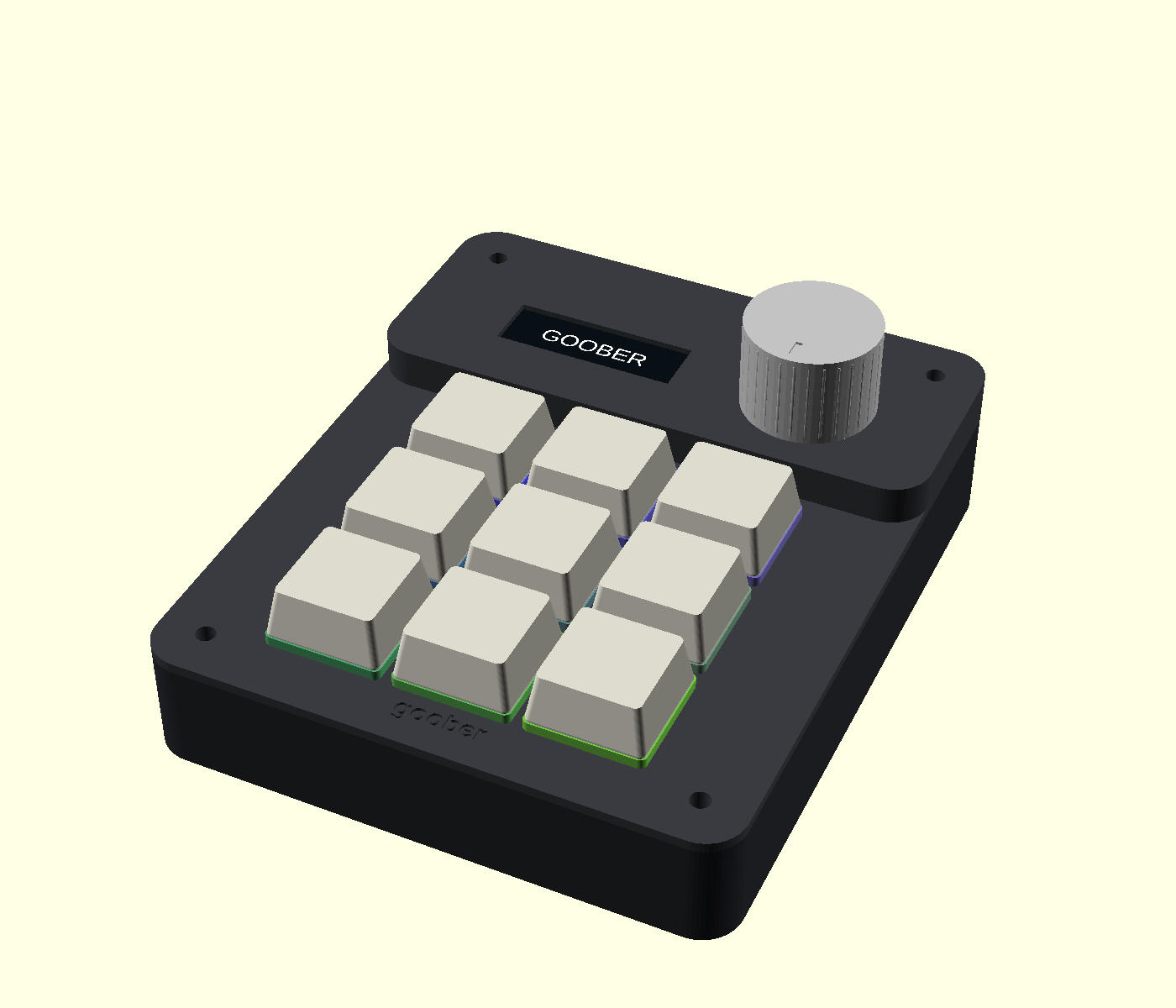
A compact 9-key USB-C macro pad with MX hot-swap switches, an OLED, a volume/mute knob and individually addressable RGB lighting. RP2040-Zero + QMK. USB hub and charging passthrough are deferred.
Rev A.1 is a checked engineering prototype, ready for a first fabrication and fit test. It has not yet been built or electrically tested on hardware.
1. Read the design plan and parts/cost list. 2. Use the fabrication guide to order a small PCB batch. 3. Print the fit coupon, then follow assembly and testing. 4. Flash the supplied UF2. Software and firmware instructions explain editing and…
Main components on the Goober
Goober bill of materials (BOM)
45 components, 16 distinct parts — part numbers from the project's BOM.
| Qty | Part | Footprint | Refs |
|---|---|---|---|
| 1 | Waveshare RP2040-Zero | RP2040_Zero_Headers | U1 |
| 1 | SN74AHCT125D | SOIC-14_3.9x8.7mm_P1.27mm | U2 |
| 1 | AO3401A P-MOSFET | SOT-23 | Q1 |
| 1 | MMBT3904 NPN | SOT-23 | Q2 |
| 1 | OLED: GND 3V3 SCL SDA | PinHeader_1x04_P2.54mm_Vertical | J1 |
| 1 | ALPS EC11E15244G1 | RotaryEncoder_Alps_EC11E-Switch_Vertical_H20mm | ENC1 |
| 1 | 1206L050YR 0.5A PTC | Fuse_1206_3216Metric | F1 |
| 9 | Kailh CPG151101S11 | SW_MX_HS_CPG151101S11_1u | SW1, SW2, SW3, SW4, SW5, SW6, SW7, SW8 +1 |
| 9 | SK6812MINI-E | LED_SK6812MINI-E_3.2x2.8mm_P1.5mm_ReverseMount | D1, D2, D3, D4, D5, D6, D7, D8 +1 |
| 10 | 100nF 16V X7R | C_0805_2012Metric | C1, C2, C3, C4, C5, C6, C7, C8 +2 |
| 1 | 4.7uF 16V X5R | C_0805_2012Metric | C11 |
| 2 | 100K 100k | R_0805_2012Metric | R1, R3 |
| 1 | 10K 10k | R_0805_2012Metric | R2 |
| 1 | 330R | R_0805_2012Metric | R4 |
| 3 | 4.7K 4.7k | R_0805_2012Metric | R5, R6, R9 |
| 2 | 3.3K 3.3k | R_0805_2012Metric | R7, R8 |
Goober design files
The KiCad project lives in the maxthorson/goober repository on GitHub; these links point at the commit this page was built from.
Goober: common questions
What microcontroller does the Goober use?
The Goober is built around the Waveshare RP2040-Zero, from the RP2040/RP2350 family.
How big is the Goober PCB?
The Goober measures 80 × 96 mm, has 2 copper layers and is 1.6 mm thick.
How many components are on the Goober?
45 components, from 16 distinct parts, with part numbers taken from the project's own BOM. The full bill of materials is listed on this page.
Where can I download the Goober design files?
From the maxthorson/goober repository on GitHub, which has the KiCad layout, the schematic and the BOM; the links under Design files point to each one.
Can I use the Goober design in my own project?
The repository has no license, so all rights stay with maxthorson. Use it as a reference, and ask the author before reusing the design.
Can I test firmware for the Goober without the hardware?
Yes. HardLabs builds a simulation of the board from its netlist and BOM, so you can run and debug RP2040/RP2350 firmware against it before you order a PCB.
Similar boards
 RP2040/RP2350
Open Book Abridged Edition
joeycastillo
85 × 115 mm29 parts2LCC-BY-SA-4.08.1k RP2040/RP2350
Corne
foostan
277.2 × 107.5 mm164 parts2LCC-BY-4.07.7k RP2040/RP2350
Corne
277.2 × 107.5 mm164 parts2LCC-BY-4.07.7k RP2040/RP2350
LogicAnalyzer
gusmanb
57 × 55.2 mm6 parts2LGPL-3.05.0k RP2040/RP2350
Jitx design
55.5 × 65 mm26 parts4LGPL-3.05.0k RP2040/RP2350
Pro V2
kata0510
290.1 × 130 mm270 parts2LMIT2.3k