
A7139-Breakout


About the A7139-Breakout
A7139-Breakout is an open source PCB design by mcauser, published on GitHub under the MIT license. It is a 2-layer board measuring 17.8 × 22 mm, with 2 components from 2 distinct parts.
Other key parts include the A7139. By type, the board carries 1 IC and 1 connector.
It belongs with the rf & radio and dev boards & breakouts designs in this gallery.
From the project
Breakout board for the A7139 433MHz RF transceiver module
Breakout board for the AMICCOM A7139 433MHz RF transceiver module.
3x boards for $3.05 (2 oz copper, 0.8mm thickness)
Only component you need is 1x7 straight or right-angle 2.54mm headers.
A7139 433MHz RF transceiver module A7139 RF transceiver chip * Order the board on OSH Park
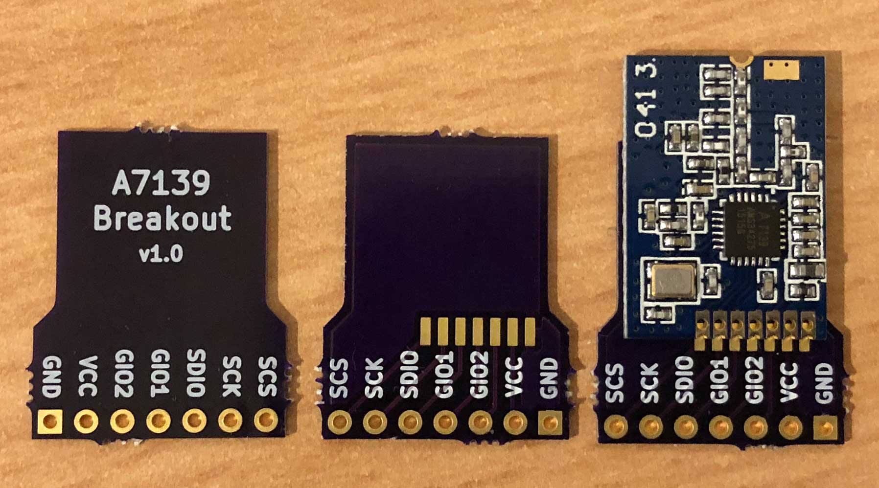
Main components on the A7139-Breakout
A7139-Breakout bill of materials (BOM)
2 components, 2 distinct parts.
| Qty | Part | Footprint | Refs |
|---|---|---|---|
| 1 | A7139 | A7139-Module | U1 |
| 1 | Conn_01x07_Male | CustomPinHeader_1x07_P2.54mm_Vertical | J1 |
A7139-Breakout design files
The KiCad project lives in the mcauser/A7139-Breakout repository on GitHub; these links point at the commit this page was built from.
A7139-Breakout: common questions
How big is the A7139-Breakout?
The A7139-Breakout measures 17.8 × 22 mm, has 2 copper layers and is 0.8 mm thick.
How many components are on the A7139-Breakout?
2 components, from 2 distinct parts. The full bill of materials is listed on this page.
Where can I download the A7139-Breakout design files?
From the mcauser/A7139-Breakout repository on GitHub, which has the KiCad layout; the links under Design files point to each one.
Can I use the A7139-Breakout design in my own project?
Yes, under the terms of its MIT license, which mcauser chose for the repository.
Similar boards
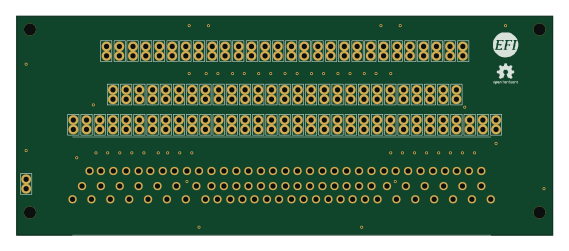
88 Pin Vag Breakout
rusefi
142 × 58 mm91 parts2LGPL-3.01.2k
134pin 7-967288-1
139.7 × 73.7 mm38 parts2LGPL-3.01.2k
Breakout 60pin EEC-IV
139.7 × 62.2 mm15 parts2LGPL-3.01.2k
Breakout 112pin Connector
174 × 58 mm39 parts2LGPL-3.01.2k
Eecv breakout
140.8 × 53.7 mm9 parts4LGPL-3.01.2k
Rj45 breakout
rene-dev
15.2 × 53.8 mm3 parts2LGPL-3.0979