
THCAD-reader+Digital-IO

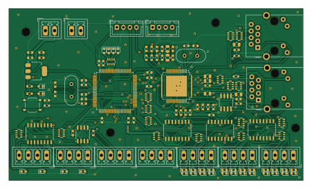
About the THCAD-reader+Digital-IO PCB
THCAD-reader+Digital-IO is an open source STM32 PCB design by MetalMusings, published on GitHub. It is a 2-layer board measuring 112.5 × 65.6 mm, with 135 components from 52 distinct parts.
Its main chip is the STM32F407VGT6, from the STM32 family. Other key parts include the TLP292-4, AT24CS32-SSHM, LAN9252_PT, MAX3485CSA/ESA and AMS1117-3.3. By type, the board carries 34 diodes, 34 resistors, 32 capacitors, 14 connectors, 9 ICs and 2 crystals.
It belongs with the robotics & motion designs in this gallery.
From the project
Documentation accompanying the "Make My Own EtherCAT device" video serie on Youtube.
This repository contains the EtherCAT devices I have designed, built and put in use in linuxcnc.
Everything should be here: - Schematics, PCB layouts, and what is needed to build the boards. - Software tools to create an ESI-file and program the ESC eeprom. - Software tools to create the application running on a STM32F407VG. - A big learning curve is hidden in here as well
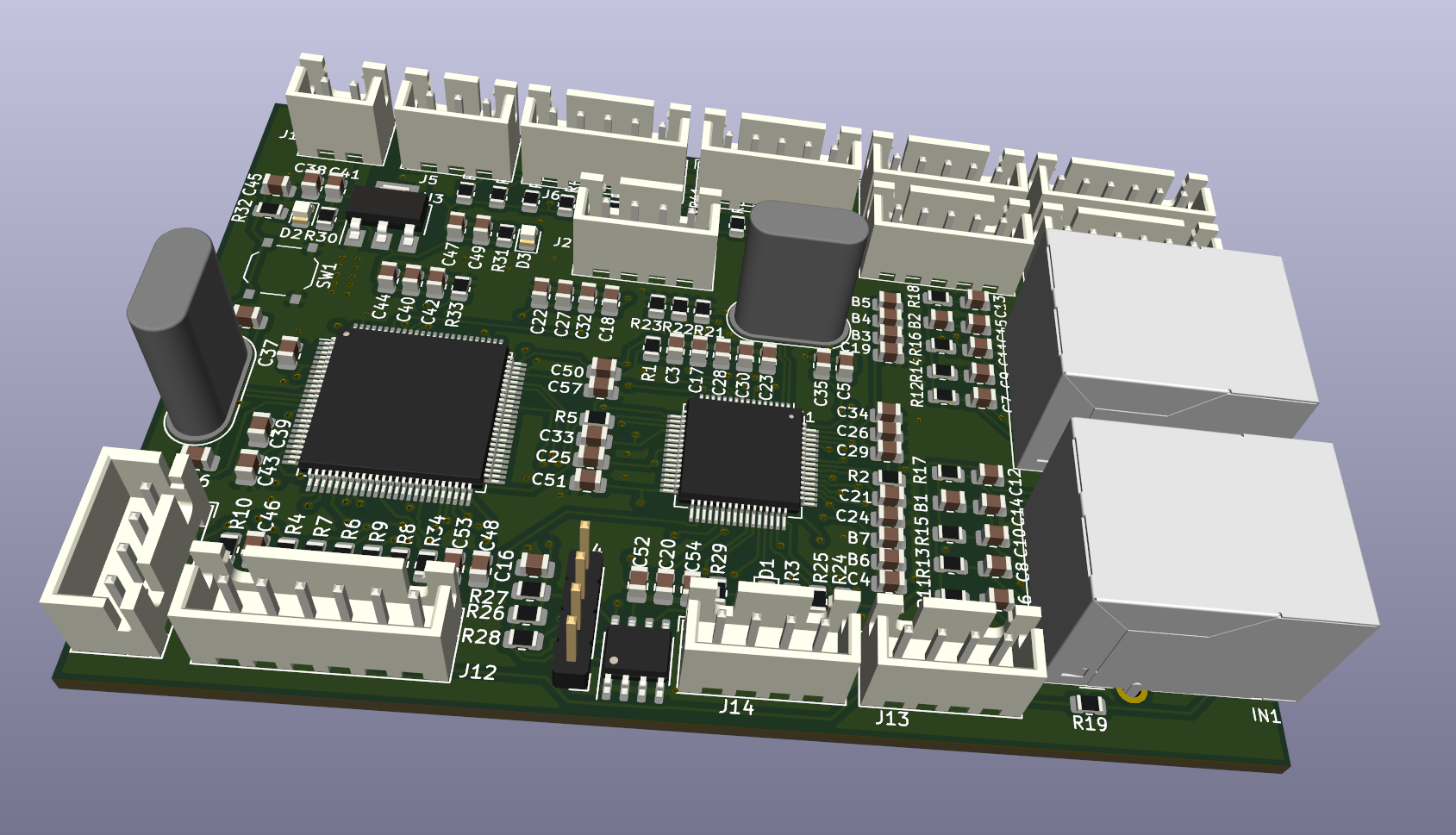
Main components on the THCAD-reader+Digital-IO
THCAD-reader+Digital-IO bill of materials (BOM)
135 components, 52 distinct parts.
| Qty | Part | Footprint | Refs |
|---|---|---|---|
| 4 | TLP292-4 | SOIC-16_4.55x10.3mm_P1.27mm | U1, U3, U4, U8 |
| 1 | AT24CS32-SSHM | SOIC-8_3.9x4.9mm_P1.27mm | U2 |
| 1 | LAN9252_PT | TQFP-64-1EP_10x10mm_P0.5mm_EP8x8mm | U5 |
| 1 | STM32F407VGT6 | LQFP-100_14x14mm_P0.5mm | U6 |
| 1 | MAX3485CSA/ESA | SO-8_3.9x4.9mm_P1.27mm | U7 |
| 1 | AMS1117-3.3 | SOT-223-3_TabPin2 | U9 |
| 1 | 25MHz | Crystal_HC49-4H_Vertical | Y1 |
| 1 | 8 MHz | Crystal_HC49-4H_Vertical | Y2 |
| 2 | 10pF | R_Array_Convex_4x0603 | CN1, CN2 |
| 1 | 0.1uF | R_Array_Convex_4x0603 | CN3 |
| 1 | In1-4 | PhoenixContact_MCV_1,5_4-G-3.5_1x04_P3.50mm_Vertical | J1 |
| 1 | In5-8 | PhoenixContact_MCV_1,5_4-G-3.5_1x04_P3.50mm_Vertical | J2 |
| 1 | In9-12 | PhoenixContact_MCV_1,5_4-G-3.5_1x04_P3.50mm_Vertical | J3 |
| 1 | 24V_Common | PhoenixContact_MCV_1,5_4-G-3.5_1x04_P3.50mm_Vertical | J4 |
| 1 | Serial usart1 | JST_XH_B4B-XH-A_1x04_P2.50mm_Vertical | J5 |
| 1 | THCAD | PhoenixContact_MCV_1,5_4-G-3.5_1x04_P3.50mm_Vertical | J6 |
| 1 | STLINK | JST_XH_B4B-XH-A_1x04_P2.50mm_Vertical | J7 |
| 1 | Output1-2 | PhoenixContact_MCV_1,5_4-G-3.5_1x04_P3.50mm_Vertical | J8 |
| 1 | 24V Field | PhoenixContact_MCV_1,5_2-G-3.5_1x02_P3.50mm_Vertical | J9 |
| 1 | Output3-4 | PhoenixContact_MCV_1,5_4-G-3.5_1x04_P3.50mm_Vertical | J10 |
Show 32 more
| Qty | Part | Footprint | Refs |
|---|---|---|---|
| 1 | 5V input | PhoenixContact_MCV_1,5_2-G-3.5_1x02_P3.50mm_Vertical | J11 |
| 7 | BLM18EG221S | C_0805_2012Metric | B1, B2, B3, B4, B5, B6, B7 |
| 2 | J0011D01BNL | PulseJack JB0011D01BNL | IN1, OUT1 |
| 1 | SW_Push | SW_Push_1P1T_XKB_TS-1187A | SW1 |
| 12 | Yellow led | LED_0603_1608Metric | D1, D3, D5, D7, D9, D11, D13, D15 +4 |
| 13 | Red led | LED_0603_1608Metric | D2, D4, D6, D8, D10, D12, D14, D16 +5 |
| 1 | Green led | LED_0603_1608Metric | D25 |
| 1 | Orange led | LED_0603_1608Metric | D26 |
| 1 | Blue led | LED_0603_1608Metric | D28 |
| 4 | White | LED_0603_1608Metric | D29, D30, D31, D34 |
| 2 | Blue | LED_0603_1608Metric | D32, D33 |
| 21 | 0.1uF | C_0603_1608Metric | C1, C2, C3, C6, C8, C10, C12, C14 +13 |
| 2 | 20pF | C_0603_1608Metric | C4, C5 |
| 1 | 2uF | C_0603_1608Metric | C7 |
| 1 | 1uF | C_0603_1608Metric | C9 |
| 1 | 470pF | C_0603_1608Metric | C11 |
| 2 | 2.2uF | C_0603_1608Metric | C13, C17 |
| 2 | 22pF | C_0603_1608Metric | C26, C27 |
| 2 | 10uF | C_0603_1608Metric | C29, C31 |
| 4 | 1k | R_0603_1608Metric | R1, R2, R3, R17 |
| 3 | 2k | R_0603_1608Metric | R4, R5, R19 |
| 1 | 12.1k | R_0603_1608Metric | R6 |
| 2 | 22 | R_0603_1608Metric | R7, R8 |
| 7 | 10k | R_0603_1608Metric | R9, R10, R11, R12, R13, R14, R15 |
| 1 | 120 | R_0603_1608Metric | R16 |
| 1 | 4k7 | R_0603_1608Metric | R18 |
| 1 | 100k | R_0603_1608Metric | R100 |
| 4 | 1k | R_Array_Convex_4x0603 | RN1, RN3, RN8, RN12 |
| 4 | 4k7 | R_Array_Convex_4x0603 | RN2, RN4, RN7, RN14 |
| 2 | 49.9 | R_Array_Convex_4x0603 | RN5, RN6 |
| 3 | 39k | R_Array_Convex_4x0603 | RN9, RN10, RN11 |
| 1 | 330 | R_Array_Convex_4x0603 | RN13 |
THCAD-reader+Digital-IO design files
The KiCad project lives in the MetalMusings/MyOwnEtherCATDevice repository on GitHub; these links point at the commit this page was built from.
THCAD-reader+Digital-IO: common questions
What microcontroller does the THCAD-reader+Digital-IO use?
The THCAD-reader+Digital-IO is built around the STM32F407VGT6, from the STM32 family.
How big is the THCAD-reader+Digital-IO PCB?
The THCAD-reader+Digital-IO measures 112.5 × 65.6 mm, has 2 copper layers and is 1.6 mm thick.
How many components are on the THCAD-reader+Digital-IO?
135 components, from 52 distinct parts. The full bill of materials is listed on this page.
Where can I download the THCAD-reader+Digital-IO design files?
From the MetalMusings/MyOwnEtherCATDevice repository on GitHub, which has the KiCad layout and the schematic; the links under Design files point to each one.
Can I use the THCAD-reader+Digital-IO design in my own project?
The repository has no license, so all rights stay with MetalMusings. Use it as a reference, and ask the author before reusing the design.
Can I test firmware for the THCAD-reader+Digital-IO without the hardware?
Yes. HardLabs builds a simulation of the board from its netlist and BOM, so you can run and debug STM32 firmware against it before you order a PCB.
More boards in MyOwnEtherCATDevice
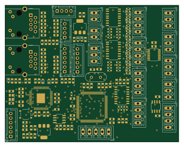 STM32
Ax58100-stm32-ethercat
94.5 × 74.5 mm184 parts2LNo license93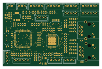 STM32
Ethercat stm32
89.9 × 59.2 mm134 parts4LNo license93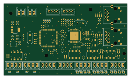 STM32
EaserCAT-7000
112.5 × 65.6 mm134 parts2LNo license93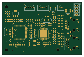 STM32
THCAD-reader
89.2 × 58.9 mm123 parts2LNo license93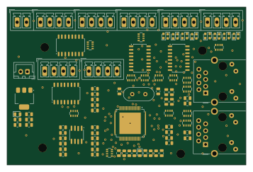
8In-8Out-LAN9252-only
89.2 × 58.9 mm95 parts2LNo license93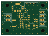
THTIC2
41.5 × 30.5 mm23 parts2LNo license93
THTIC
41.5 × 30.5 mm23 parts2LNo license93
THCLIP
47.3 × 35.4 mm8 parts2LNo license93
Similar boards
 STM32
LumenPnP Motherboard
opulo-inc
149 × 95 mm296 parts4LCC-BY-SA-4.03.7k STM32
Base
google
52.3 × 52.3 mm36 parts2LApache-2.02.9k STM32
Type g
169 × 30 mm24 parts2LApache-2.02.9k STM32
Main panel
234 × 84 mm26 parts4LApache-2.02.9k STM32
Type a
150 × 30 mm14 parts2LApache-2.02.9k STM32
Type c
188 × 30 mm17 parts2LApache-2.02.9k