
Kiwi

About the Kiwi PCB
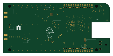
Kiwi is an open source FPGA PCB design by mfkiwl, published on GitHub. It is a board measuring 117 × 55 mm, with 166 components from 59 distinct parts.
Its main chip is the XC7A35T-1FTG256C, from the FPGA family. Other key parts include the SE4150L-R, LP5907QMFX-3.3Q1, CAT24C256YI-GT3, LTC2248 and CWX823-066.6666M. By type, the board carries 94 capacitors, 19 resistors, 13 inductors, 12 ICs, 10 test points and 6 connectors.
It belongs with the rf & radio and audio designs in this gallery.
From the project
KiCAD PCB files for KiwiSDR project including active antenna and bias tee
Software-defined Radio (SDR) and GPS for the BeagleBone Black ----------------------------------------------------------------------
An add-on board ("cape") that turns your Beagle into a web-accessible shortwave receiver.
This repository contains the KiCAD files (schematics, board layout), Gerbers, BOM and other files used to produce the KiwiSDR PCB. Also included here is the design for an active antenna and bias tee although they are still undergoing development.

Main components on the Kiwi
Kiwi bill of materials (BOM)
166 components, 59 distinct parts — part numbers from the project's BOM.
| Qty | Part | Footprint | Refs |
|---|---|---|---|
| 1 | XC7A35T-1FTG256C Artix-7 A35 Xilinx | kiwi-FTG256 | U1 |
| 1 | SE4150L-R SE4150L Skyworks Solutions | kiwi-QFN24 | U101 |
| 2 | LP5907QMFX-3.3Q1 LP5907 3.3V 250mA Texas Instruments | kiwi-SOT23_5 | U104, U404 |
| 1 | CAT24C256YI-GT3 EEPROM 32Kx8 ON Semiconductor | kiwi-TSSOP8 | U301 |
| 1 | LTC2248 Linear Technology | kiwi-QFN32 | U401 |
| 1 | CWX823-066.6666M 66.6666 MHz Connor-Winfield | kiwi-XO | U402 |
| 2 | NC7SZ125P5X NC7SZ125 Fairchild Semiconductor | kiwi-SC70_5 | U403, U406 |
| 1 | LTC6401-20 Linear Technology | kiwi-QFN16 | U405 |
| 1 | LMR10530YSD/NOPB LMR10530Y 1.0V 3A Texas Instruments | kiwi-WSON10 | U701 |
| 1 | LP5907QMFX-1.8Q1 LP5907 1.8V 250mA Texas Instruments | kiwi-SOT23_5 | U702 |
| 1 | 7Q-16.368MBG-T 16.368 MHz TXC | kiwi-TCXO | X101 |
| 1 | TB_2 | kiwi-TB_2P_2_54MM | J1 |
| 2 | SMA | kiwi-SMA_OPL_EM | J2, J3 |
| 2 | DNL U.FL | kiwi-U.FL | J4, J5 |
| 1 | POWER JACK 2.1MM | kiwi-JACK_2_1MM_TH | J6 |
| 1 | SF1186G SAW L1 Murata | kiwi-SAW | FL101 |
| 1 | LOGO | kiwi-KIWI_10MM | GFX1 |
| 1 | SRF0905A-501Y CMC 500uH 1A Bourns | kiwi-CMC | T301 |
| 5 | TEST_POINT | kiwi-TP_600 | TP101, TP105, TP401, TP701, TP702 |
| 3 | TEST_POINT | kiwi-TP_VIA_1250 | TP102, TP103, TP104 |
Show 39 more
| Qty | Part | Footprint | Refs |
|---|---|---|---|
| 2 | TEST_POINT | kiwi-TP_VIA_600 | TP301, TP402 |
| 2 | CDSOD323-T03C TVS 3.3V Bourns | kiwi-SOD323 | Z401, Z402 |
| 1 | HEADER 13x2 | kiwi-BEAGLEBONE_BLACK | ZB1 |
| 1 | BMI-S-209-F RF_SHIELD 29x19 Laird | kiwi-RF_SHIELD_29x19_16P | ZR101 |
| 2 | BMI-S-209-C RF_SHIELD_COVER 29x19 Laird | kiwi-RF_SHIELD_COVER | ZR102, ZR402 |
| 1 | BMI-S-209-F RF_SHIELD 29x19 Laird | kiwi-RF_SHIELD_29x19 | ZR401 |
| 1 | SSB44-E3/52T SR 5A 40V Vishay | kiwi-DO214_AA | D701 |
| 1 | MLK1005S39NJ 39nH TDK | kiwi-SM0402 | L101 |
| 5 | MMZ1005B601C FB 600Z TDK | kiwi-SM0402 | L102, L103, L104, L407, L408 |
| 2 | MLG1005SR33J 330nH TDK | kiwi-SM0402 | L401, L404 |
| 1 | MLG1005SR27J 270nH TDK | kiwi-SM0402 | L402 |
| 3 | MLG1005SR15J 150nH TDK | kiwi-SM0402 | L403, L405, L406 |
| 1 | SRN4018-1R0Y 1uH 3.7A Bourns | kiwi-INDUCTOR_4x4 | L701 |
| 28 | GRM155R6YA474KE01D 470n Murata | kiwi-SM0402 | C1, C2, C3, C6, C7, C8, C11, C12 +20 |
| 4 | GRM31CR60J107ME39L 100u Murata | kiwi-SM1206 | C5, C20, C29, C703 |
| 11 | GRM155R60J475ME47D 4.7u Murata | kiwi-SM0402 | C9, C14, C17, C18, C27, C28, C34, C35 +3 |
| 2 | GRM1555C1H220JA01D 22p Murata | kiwi-SM0402 | C101, C104 |
| 8 | GRM155R71C103KA01D 10n Murata | kiwi-SM0402 | C105, C106, C193, C303, C305, C413, C417, C425 |
| 1 | DNL 10n | kiwi-SM0402 | C107 |
| 14 | GRM155R71C104KA88D 100n Murata | kiwi-SM0402 | C190, C191, C192, C195, C301, C421, C422, C423 +6 |
| 4 | GRM1555C1H101JA01D 100p Murata | kiwi-SM0402 | C194, C408, C411, C416 |
| 7 | GRM155R61E105KA12D 1u Murata | kiwi-SM0402 | C196, C197, C418, C419, C426, C427, C705 |
| 2 | GRM1555C2A560JA01D 56p/100 Murata | kiwi-SM0402 | C401, C404 |
| 2 | GRM1555C1H161JA01D 160p/50 Murata | kiwi-SM0402 | C402, C403 |
| 1 | GRM219R72A102KA01J 1n/100 Murata | kiwi-SM0805 | C405 |
| 1 | ESD61C474K4T2A-28 470n/100 AVX | kiwi-SM1206 | C406 |
| 5 | GCM155R71H102KA37D 1n Murata | kiwi-SM0402 | C407, C409, C428, C430, C432 |
| 3 | GRM155R60J225ME15D 2.2u Murata | kiwi-SM0402 | C412, C415, C420 |
| 1 | GRM21BR60J226ME39L 22u Murata | kiwi-SM0805 | C701 |
| 4 | ERJ-2RKF1000X 100R Panasonic | kiwi-SM0402 | R101, R102, R103, R401 |
| 3 | ERJ-2RKF5601X 5K6 Panasonic | kiwi-SM0402 | R303, R304, R305 |
| 1 | ERJ-2RKF66R5X 66R5 Panasonic | kiwi-SM0402 | R402 |
| 1 | ERJ-2RKF28R7X 28R7 Panasonic | kiwi-SM0402 | R403 |
| 2 | CAY16-101J8LF 100R Bourns | kiwi-RNET_CAY16_J8 | R404, R405 |
| 4 | ERJ-2RKF1002X 10K Panasonic | kiwi-SM0402 | R406, R409, R410, R703 |
| 1 | DNL | kiwi-SM0402 | R407 |
| 1 | ERJ-2GE0R00X 0R Panasonic | kiwi-SM0402 | R408 |
| 1 | ERJ-2RKF10R0X 10R Panasonic | kiwi-SM0402 | R701 |
| 1 | ERJ-2RKF6651X 6K65 Panasonic | kiwi-SM0402 | R702 |
Kiwi design files
The KiCad project lives in the mfkiwl/KiwiSDR_PCB repository on GitHub; these links point at the commit this page was built from.
Kiwi: common questions
What microcontroller does the Kiwi use?
The Kiwi is built around the XC7A35T-1FTG256C, from the FPGA family.
How big is the Kiwi PCB?
The Kiwi measures 117 × 55 mm and is 1.6 mm thick.
How many components are on the Kiwi?
166 components, from 59 distinct parts, with part numbers taken from the project's own BOM. The full bill of materials is listed on this page.
Where can I download the Kiwi design files?
From the mfkiwl/KiwiSDR_PCB repository on GitHub, which has the KiCad layout and the BOM; the links under Design files point to each one.
Can I use the Kiwi design in my own project?
The repository has no license, so all rights stay with mfkiwl. Use it as a reference, and ask the author before reusing the design.
Can I test firmware for the Kiwi without the hardware?
Yes. HardLabs builds a simulation of the board from its netlist and BOM, so you can run and debug FPGA firmware against it before you order a PCB.
More boards in KiwiSDR_PCB
Similar boards
 FPGA
FPGABase board
GlasgowEmbedded
80 × 49 mm222 parts4L0BSD2.2k FPGA
FPGAThunderscope Rev5.3
EEVengers
122.5 × 103.5 mm817 parts6LMIT1.3k FPGA
FPGAIcepi zero
cheyao
65 × 30 mm143 parts4LSHL-2.1828 FPGA
FPGARadioberry
pa3gsb
65 × 56 mm143 parts4LNo license675 FPGA
FPGAHaasoscopePro
drandyhaas
224.5 × 160 mm586 parts10LMIT471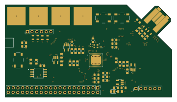 FPGA
FPGAFomu hardware
im-tomu
90 × 50 mm57 parts2LCC-BY-SA-4.0235