
I2c test board

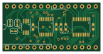
About the I2c test board
I2c test board is an open source PCB design by mike42, published on GitHub. It is a 4-layer board measuring 36.2 × 17.9 mm, with 16 components from 13 distinct parts.
Other key parts include the PCA9564, LTC6904 and SC18IS602B. By type, the board carries 7 jumpers, 3 ICs, 3 capacitors, 2 resistors and 1 connector.
It belongs with the retro computing designs in this gallery.
From the project
A 65C816-based homebrew computer (prototype)
This is a prototype 65C816-based computer. It features a 1.8432 MHz processor, 1 megabyte of static RAM, a 65C22 I/O port, and an NXP SC16C752 dual UART.
This is a learning project, and I am blogging about it as I progress.
- A first look at the 65C816 processor - 65C816 computer - initial prototype - Interfacing an NXP UART to an 8-bit computer - Let’s implement preemptive multitasking - Building an emulator for my 65C816 computer - 65C816 computer - second prototype - Building a 65C816 test board - Let’s implement power-on self test (POST) - Let’s make a bootloader – Part 1 - Let’s make a…
Main components on the I2c test board
I2c test board bill of materials (BOM)
16 components, 13 distinct parts.
| Qty | Part | Footprint | Refs |
|---|---|---|---|
| 1 | PCA9564 | TSSOP-20_4.4x6.5mm_P0.65mm | U1 |
| 1 | LTC6904 | MSOP-8_3x3mm_P0.65mm | U2 |
| 1 | SC18IS602B | TSSOP-16_4.4x5mm_P0.65mm | U3 |
| 1 | TestBoard_Socket | DIP-28_W15.24mm_Socket | J1 |
| 1 | CLK_A0_SET | SolderJumper-3_P1.3mm_Bridged12_RoundedPad1.0x1.5mm | JP1 |
| 1 | X2_OUT | SolderJumper-2_P1.3mm_Bridged_RoundedPad1.0x1.5mm | JP2 |
| 1 | CLK | SolderJumper-2_P1.3mm_Bridged_RoundedPad1.0x1.5mm | JP3 |
| 1 | CLK_INV | SolderJumper-2_P1.3mm_Bridged_RoundedPad1.0x1.5mm | JP4 |
| 1 | SPI_A0_SET | SolderJumper-3_P1.3mm_Bridged12_RoundedPad1.0x1.5mm | JP5 |
| 1 | SPI_A1_SET | SolderJumper-3_P1.3mm_Bridged12_RoundedPad1.0x1.5mm | JP6 |
| 1 | SPI_A2_SET | SolderJumper-3_P1.3mm_Bridged12_RoundedPad1.0x1.5mm | JP7 |
| 3 | C | C_0603_1608Metric_Pad1.08x0.95mm_HandSolder | C1, C2, C3 |
| 2 | R | R_0603_1608Metric_Pad0.98x0.95mm_HandSolder | R1, R2 |
I2c test board design files
The KiCad project lives in the mike42/65816-computer repository on GitHub; these links point at the commit this page was built from.
I2c test board: common questions
How big is the I2c test board?
The I2c test board measures 36.2 × 17.9 mm, has 4 copper layers and is 1.69 mm thick.
How many components are on the I2c test board?
16 components, from 13 distinct parts. The full bill of materials is listed on this page.
Where can I download the I2c test board design files?
From the mike42/65816-computer repository on GitHub, which has the KiCad layout and the schematic; the links under Design files point to each one.
Can I use the I2c test board design in my own project?
The repository has no license, so all rights stay with mike42. Use it as a reference, and ask the author before reusing the design.
More boards in 65816-computer
Similar boards
Expansion Card Retrofit
FrameworkComputer
24 × 27.3 mm5 parts2LCC-BY-4.01.1k
Rgb to hdmi
hoglet67
77 × 97 mm67 parts2LGPL-3.01.0k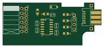
Buffer
53.9 × 23.2 mm13 parts2LGPL-3.01.0k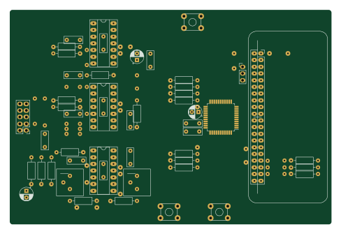
X1
121.9 × 81.3 mm51 parts2LGPL-3.01.0k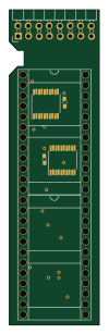
Amiga External
21.9 × 76.7 mm6 parts2LGPL-3.01.0k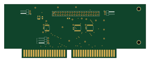
Videoslotadapter
152 × 57.6 mm13 parts2LGPL-3.01.0k