
ATV-Control

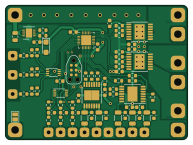
About the ATV-Control PCB
ATV-Control is an open source AVR/Arduino PCB design by mikelawrence, published on GitHub under the MIT license. It is a 2-layer board measuring 48.3 × 35.6 mm, with 74 components from 22 distinct parts.
Its main chip is the ATXMEGA8E5-M4U, from the AVR/Arduino family. Other key parts include the LT3014IDD, BTS70021EPPXUMA1, BTS70082EPAXUMA1, SN74LVC3G17DCUR and BTS72002EPAXUMA1. By type, the board carries 36 resistors, 28 capacitors, 8 ICs, 1 connector and 1 diode.
It belongs with the power & battery designs in this gallery.
From the project
ATV Control board is an electronic relay replacement control board for 20A horn and two 7.5A LED circuits.
This board was designed to act as a relay for two LED (V1 and V2) lights up to 7.5A each and a horn (H) up to 20A. Each LED Output has a control switch input and indicator LED output. When the Ignition input is on (12V) indicates the ATV is running so the Reverse input will turn LED V2 output on when at 12V and the High Beam input will turn LED V1 output on when at 12V. Turning Ignition off (0V) will turn off all LED outptus (V1 and V2). The control switches allows manual control the LED lights even when the ATV off. When you turn a LED on with a control switch the LED light will remain on…
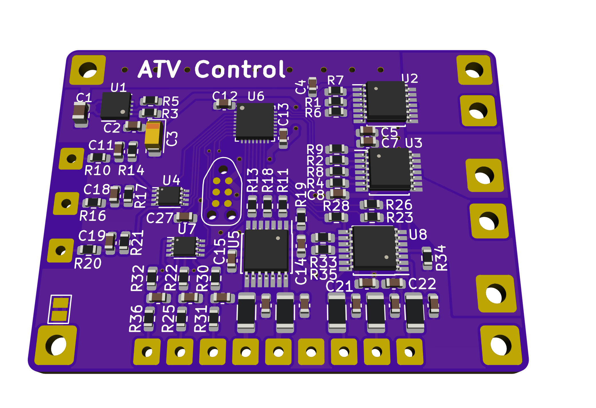
Main components on the ATV-Control
ATV-Control bill of materials (BOM)
74 components, 22 distinct parts — part numbers from the project's BOM.
| Qty | Part | Footprint | Refs |
|---|---|---|---|
| 1 | LT3014IDD Linear Tech | DFN-8-1EP_3x3mm_P0.5mm_EP1.66x2.38mm | U1 |
| 1 | BTS70021EPPXUMA1 BTS7002-1EPP Infineon | Infineon_PG-TSDSO-14-22 | U2 |
| 1 | BTS70082EPAXUMA1 BTS7008-2EPA Infineon | Infineon_PG-TSDSO-14-22 | U3 |
| 2 | SN74LVC3G17DCUR 74LVC3G17 TI | VSSOP-8_2.3x2mm_P0.5mm | U4, U7 |
| 1 | BTS72002EPAXUMA1 BTS7200-2EPA Infineon | Infineon_PG-TSDSO-14-22 | U5 |
| 1 | ATXMEGA8E5-M4U Atmel | QFN-32-1EP_4x4mm_P0.4mm_EP2.65x2.65mm | U6 |
| 1 | BTS72004EPAXUMA1 BTS7200-4EPA Infineon | Infineon_PG-TSDSO-14-22 | U8 |
| 1 | DNF | TC2030-IDC-NP | J11 |
| 1 | SM15T33CA ST | D_SMC_Handsoldering | D1 |
| 1 | GRJ21BC72A105KE11L 1uF Murata Electronics | C_0805_2012Metric | C1 |
| 4 | GRM188R71C474KA88 0.47uF Murata Electronics | C_0603_1608Metric | C2, C12, C13, C27 |
| 1 | T491A106M016AT7280 10uF Kemet | CP_EIA-3216-18_Kemet-A | C3 |
| 4 | GCJ188R92A473KA1D 47nF Murata Electronics | C_0603_1608Metric | C4, C7, C14, C21 |
| 4 | GCJ188R72A104KA1D 0.1uF Murata Electronics | C_0603_1608Metric | C5, C8, C15, C22 |
| 14 | GCM188R72A103KA7D 10nF Murata Electronics | C_0603_1608Metric | C6, C9, C10, C11, C16, C17, C18, C19 +6 |
| 8 | RC0603JR-074K7L 4.7k Yageo | R_0603_1608Metric | R1, R2, R4, R11, R13, R23, R26, R28 |
| 1 | CRCW06032M15FKEA 2.15M Vishay | R_0603_1608Metric | R3 |
| 2 | CRCW06031M27FKEA 1.27M Vishay | R_0603_1608Metric | R5, R17 |
| 8 | RC0603JR-0710KL 10k Yageo | R_0603_1608Metric | R6, R8, R18, R25, R31, R33, R34, R36 |
| 4 | RC0603FR-0747RL 47R Yageo | R_0603_1608Metric | R7, R9, R19, R35 |
Show 2 more
| Qty | Part | Footprint | Refs |
|---|---|---|---|
| 8 | RC0603JR-07100KL 100k Yageo | R_0603_1608Metric | R10, R14, R16, R20, R21, R22, R30, R32 |
| 5 | ERJ-8GEYJ561V 560R Panasonic | R_1206_3216Metric | R12, R15, R24, R27, R29 |
ATV-Control design files
The KiCad project lives in the mikelawrence/ATV-Control repository on GitHub; these links point at the commit this page was built from.
ATV-Control: common questions
What microcontroller does the ATV-Control use?
The ATV-Control is built around the ATXMEGA8E5-M4U, from the AVR/Arduino family.
How big is the ATV-Control PCB?
The ATV-Control measures 48.3 × 35.6 mm, has 2 copper layers and is 1.6 mm thick.
How many components are on the ATV-Control?
74 components, from 22 distinct parts, with part numbers taken from the project's own BOM. The full bill of materials is listed on this page.
Where can I download the ATV-Control design files?
From the mikelawrence/ATV-Control repository on GitHub, which has the KiCad layout and the BOM; the links under Design files point to each one.
Can I use the ATV-Control design in my own project?
Yes, under the terms of its MIT license, which mikelawrence chose for the repository.
Can I test firmware for the ATV-Control without the hardware?
Yes. HardLabs builds a simulation of the board from its netlist and BOM, so you can run and debug AVR/Arduino firmware against it before you order a PCB.
Similar boards
 AVR/Arduino
Redox keyboard
mattdibi
162.2 × 126.5 mm77 parts2LMIT2.0k AVR/Arduino
ModuleV450
stuartpittaway
30 × 61.4 mm39 parts2LCC-BY-NC-4.01.1k AVR/Arduino
V4
30 × 50 mm38 parts2LCC-BY-NC-4.01.1k AVR/Arduino
Discipline
coseyfannitutti
304.9 × 122.8 mm170 parts2LCC-BY-NC-4.01.0k AVR/Arduino
Megadesk
gcormier
41.7 × 32.2 mm23 parts2LGPL-3.0818 AVR/Arduino
Easyduino Atmega Nano
Hanqaqa
43.4 × 18 mm30 parts4LCERN-OHL-P-2.0746