
Rpi camera led

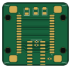
About the Rpi camera led PCB
Rpi camera led is an open source RISC-V PCB design by mithro, published on GitHub under the Apache-2.0 license. It is a 2-layer board measuring 25 × 23.9 mm, with 20 components from 16 distinct parts.
Its main chip is the WCH CH32V003A4M6 (LCSC C5346357), from the RISC-V family. By type, the board carries 9 resistors, 4 connectors, 2 transistors, 2 diodes, 2 capacitors and 1 IC.
It belongs with the sensors designs in this gallery.
From the project
Interposer for the Raspberry Pi camera flex cable: passes the 15-way CSI bus straight through and adds I2C-controlled camera GPIO, PWM illumination LEDs and an ambient light sensor, driven by a CH32V003.
An interposer for the Raspberry Pi camera flex cable (15 pin, 1.0 mm pitch FPC). It sits in the middle of the cable, passes all fifteen camera signals straight through, and adds a CH32V003A4M6 that gives the Pi I2C-controlled camera GPIO, PWM illumination LEDs and an ambient light reading.
25.0 × 23.9 mm, two layers, everything on the front. J1 (left) faces the Raspberry Pi and J2 (right) faces the camera; they sit 180° apart so the two cable segments leave opposite edges and the board drops into an existing cable run in line. The MCU is the SOIC-16 in the middle, the two white illumination…
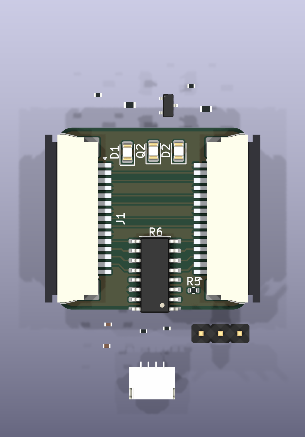
Main components on the Rpi camera led
Rpi camera led bill of materials (BOM)
20 components, 16 distinct parts.
| Qty | Part | Footprint | Refs |
|---|---|---|---|
| 1 | WCH CH32V003A4M6 (LCSC C5346357) CH32V003A4M6 | SOIC-16_3.9x9.9mm_P1.27mm | U1 |
| 1 | AO3400A | SOT-23 | Q1 |
| 1 | e.g. Everlight PT17-21C/L41/TR8 Phototransistor | LED_0805_2012Metric | Q2 |
| 1 | JUSHUO AFA07-S15FCA-00 (LCSC C262721) / Amphenol SFW15R-1STE1LF FFC 15P 1.0mm bottom contact (to Raspberry Pi) | JUSHUO_AFA07-S15FCA-00_1x15-1MP_P1.0mm_Horizontal | J1 |
| 1 | JUSHUO AFA07-S15ECA-00 (LCSC C262742) / Amphenol SFW15R-2STE1LF FFC 15P 1.0mm top contact (to camera) | JUSHUO_AFA07-S15ECA-00_1x15-1MP_P1.0mm_Horizontal | J2 |
| 1 | JST SM04B-SRSS-TB or SH1.0-4P clone Qwiic (JST SH 1.0mm) | JST_SH_SM04B-SRSS-TB_1x04-1MP_P1.00mm_Horizontal | J3 |
| 1 | SWD program header 2.54mm | PinHeader_1x03_P2.54mm_Vertical | J4 |
| 2 | White 0805/2835, e.g. Hongli/NationStar White LED | LED_0805_2012Metric | D1, D2 |
| 1 | 100nF | C_0402_1005Metric | C1 |
| 1 | 1uF | C_0402_1005Metric | C2 |
| 2 | 4.7k | R_0402_1005Metric | R1, R2 |
| 2 | 10R | R_0603_1608Metric | R3, R4 |
| 1 | 100R | R_0402_1005Metric | R5 |
| 2 | 0 | R_0402_1005Metric | R6, R7 |
| 1 | 10k | R_0402_1005Metric | R8 |
| 1 | 47k | R_0402_1005Metric | R9 |
Rpi camera led design files
The KiCad project lives in the mithro/rpi-camera-led repository on GitHub; these links point at the commit this page was built from.
Rpi camera led: common questions
What microcontroller does the Rpi camera led use?
The Rpi camera led is built around the WCH CH32V003A4M6 (LCSC C5346357), from the RISC-V family.
How big is the Rpi camera led PCB?
The Rpi camera led measures 25 × 23.9 mm, has 2 copper layers and is 1.6 mm thick.
How many components are on the Rpi camera led?
20 components, from 16 distinct parts. The full bill of materials is listed on this page.
Where can I download the Rpi camera led design files?
From the mithro/rpi-camera-led repository on GitHub, which has the KiCad layout and the schematic; the links under Design files point to each one.
Can I use the Rpi camera led design in my own project?
Yes, under the terms of its Apache-2.0 license, which mithro chose for the repository.
Can I test firmware for the Rpi camera led without the hardware?
Yes. HardLabs builds a simulation of the board from its netlist and BOM, so you can run and debug RISC-V firmware against it before you order a PCB.
Similar boards
 RISC-V
Workbench-1 Controller
Quchaosheng
160 × 130 mm106 parts8LApache-2.0129 RISC-V
Keytartouch
cnlohr
152.5 × 117.5 mm69 parts2LMIT105 RISC-V
Froggyswadge
81.5 × 72.2 mm92 parts2LMIT105 RISC-V
Ch32v003f4u6 with wsled
40.6 × 44.5 mm26 parts2LMIT105 RISC-V
NorthPoleCircuit
Janky-Jingle-Crew
150 × 110 mm46 parts4LNo license62 RISC-V
Osc sg90-v006
OpenServoCore
20.6 × 9.6 mm26 parts4LApache-2.034