
Frequency Reference Distribution

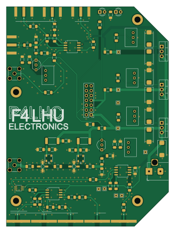
About the Frequency Reference Distribution PCB
Frequency Reference Distribution is an open source PCB design by molendijk, published on GitHub. It is a 2-layer board measuring 85.3 × 115 mm, with 100 components from 41 distinct parts.
Other key parts include the 551MLFT, LT1085-ADJ and 74LVC74. By type, the board carries 34 resistors, 31 capacitors, 13 connectors, 7 ICs, 4 test points and 2 transistors.
It belongs with the rf & radio and dev boards & breakouts designs in this gallery.
From the project
KiCad Design of a 10MHz Frequency reference distributor and derived 25MHz distributor.
This hardware project is intended for people posessing a 10MHz sinusoidal reference oscillator (GPS DO / Rubidium Source) but require a 25MHz reference for use with an SDR (Adalm-Pluto), ADF4351 (Evaluation board) or a LNB (modified Bulls-Eye).
https://www.analog.com/en/resources/evaluation-hardware-and-software/evaluation-boards-kits/adalm-pluto.html https://github.com/molendijk/QO100LOADF4351_Loader https://3b8mars.org/wp-content/uploads/2023/10/Bulleye-LNB-modification-for-external-clocking-updated-Oct2023.pdf

Main components on the Frequency Reference Distribution
Frequency Reference Distribution bill of materials (BOM)
100 components, 41 distinct parts — part numbers from the project's BOM.
| Qty | Part | Footprint | Refs |
|---|---|---|---|
| 3 | 551MLFT | SOIC-8_5.3x6.2mm_P1.27mm | U1, U8, U9 |
| 3 | LT1085-ADJ | TO-220-3_Vertical | U2, U3, U6 |
| 1 | 74LVC74 | SSOP-8_2.95x2.8mm_P0.65mm | U7 |
| 2 | 2N2222 | TO-92_Inline_Wide | Q1, Q2 |
| 3 | MHz 10 | SMA_Amphenol_132289_EdgeMount | J1, J2, J3 |
| 1 | MHz 10 Source | SMA_Amphenol_132289_EdgeMount | J4 |
| 1 | MHz 10 LPF | SMA_Amphenol_132134-11_Vertical | J5 |
| 1 | CONN_02X07_ODD_EVEN Conn_02x07_Odd_Even | PinHeader_2x07_P2.54mm_Vertical | J6 |
| 1 | MHz 50 LPF | SMA_Amphenol_132134-11_Vertical | J7 |
| 1 | Jack-DC | BarrelJack_Horizontal | J8 |
| 4 | MHz 25 | SMA_Amphenol_132289_EdgeMount | J9, J10, J11, J12 |
| 1 | MHz 50 | SMA_Amphenol_132289_EdgeMount | J13 |
| 1 | MHZ50_A | TestPoint_THTPad_1.5x1.5mm_Drill0.7mm | TP1 |
| 2 | Gnd | TestPoint_THTPad_1.5x1.5mm_Drill0.7mm | TP2, TP3 |
| 1 | MHZ50_B | TestPoint_THTPad_1.5x1.5mm_Drill0.7mm | TP4 |
| 1 | Gnd | TestPoint_THTPad_1.5x1.5mm_Drill0.7mm | TP_GND1 |
| 1 | +3.3V | TestPoint_THTPad_1.5x1.5mm_Drill0.7mm | TP_P3V3 |
| 1 | +5V | TestPoint_THTPad_1.5x1.5mm_Drill0.7mm | TP_P5V1 |
| 1 | +15V | TestPoint_THTPad_1.5x1.5mm_Drill0.7mm | TP_P15V1 |
| 1 | +16V | TestPoint_THTPad_1.5x1.5mm_Drill0.7mm | TP_VBUS1 |
Show 21 more
| Qty | Part | Footprint | Refs |
|---|---|---|---|
| 2 | LED | LED_D3.0mm | D1, D2 |
| 2 | TCCH-80+ | Minicircuits_GU1604 | L1, L2 |
| 4 | 10NF 10nF | C_1206_3216Metric_Pad1.33x1.80mm_HandSolder | C1, C14, C15, C16 |
| 4 | 100NF 100nF | C_1206_3216Metric_Pad1.33x1.80mm_HandSolder | C2, C19, C21, C23 |
| 14 | 39NF 39nF | C_1206_3216Metric_Pad1.33x1.80mm_HandSolder | C3, C4, C5, C8, C12, C18, C20, C22 +6 |
| 3 | 47UF 47uF | CP_EIA-7343-31_Kemet-D_HandSolder | C6, C11, C24 |
| 3 | 22UF 22uF | CP_EIA-7343-31_Kemet-D_HandSolder | C7, C9, C10 |
| 2 | 1UF 1uF | C_1206_3216Metric_Pad1.33x1.80mm_HandSolder | C13, C17 |
| 1 | 10UF 10uF | CP_EIA-7343-31_Kemet-D_HandSolder | C25 |
| 1 | 220R | R_1206_3216Metric_Pad1.30x1.75mm_HandSolder | R1 |
| 1 | 330R | R_1206_3216Metric_Pad1.30x1.75mm_HandSolder | R2 |
| 4 | 100 | R_1206_3216Metric_Pad1.30x1.75mm_HandSolder | R3, R6, R21, R30 |
| 13 | 30 | R_1206_3216Metric_Pad1.30x1.75mm_HandSolder | R4, R7, R8, R11, R25, R26, R27, R28 +5 |
| 2 | 5k | Potentiometer_Bourns_3299W_Vertical | R5, R23 |
| 2 | 5K1 5k1 | R_1206_3216Metric_Pad1.30x1.75mm_HandSolder | R9, R24 |
| 3 | 00 | R_1206_3216Metric_Pad1.30x1.75mm_HandSolder | R10, R14, R22 |
| 2 | 500R | Potentiometer_Bourns_3299W_Vertical | R12, R17 |
| 3 | 120R | R_1206_3216Metric_Pad1.30x1.75mm_HandSolder | R13, R16, R18 |
| 1 | 2k | Potentiometer_Bourns_3299W_Vertical | R15 |
| 1 | 300 | R_2512_6332Metric_Pad1.40x3.35mm_HandSolder | R19 |
| 1 | 160 | R_2512_6332Metric_Pad1.40x3.35mm_HandSolder | R20 |
Frequency Reference Distribution design files
The KiCad project lives in the molendijk/Frequency-Reference repository on GitHub; these links point at the commit this page was built from.
- LayoutFreq_Reference.kicad_pcb
- SchematicFreq_Reference.kicad_sch
- BOMFreq_Reference.csv
Frequency Reference Distribution: common questions
How big is the Frequency Reference Distribution PCB?
The Frequency Reference Distribution measures 85.3 × 115 mm, has 2 copper layers and is 1.6 mm thick.
How many components are on the Frequency Reference Distribution?
100 components, from 41 distinct parts, with part numbers taken from the project's own BOM. The full bill of materials is listed on this page.
Where can I download the Frequency Reference Distribution design files?
From the molendijk/Frequency-Reference repository on GitHub, which has the KiCad layout, the schematic and the BOM; the links under Design files point to each one.
Can I use the Frequency Reference Distribution design in my own project?
The repository has no license, so all rights stay with molendijk. Use it as a reference, and ask the author before reusing the design.
More boards in Frequency-Reference
Similar boards
88 Pin Vag Breakout
rusefi
142 × 58 mm91 parts2LGPL-3.01.2k
134pin 7-967288-1
139.7 × 73.7 mm38 parts2LGPL-3.01.2k
Breakout 60pin EEC-IV
139.7 × 62.2 mm15 parts2LGPL-3.01.2k
Breakout 112pin Connector
174 × 58 mm39 parts2LGPL-3.01.2k
Eecv breakout
140.8 × 53.7 mm9 parts4LGPL-3.01.2k
Rj45 breakout
rene-dev
15.2 × 53.8 mm3 parts2LGPL-3.0979