
MOS CPU Replacer

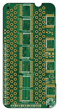
About the MOS CPU Replacer PCB
MOS CPU Replacer is an open source PCB design by monotech, published on GitHub. It is a 4-layer board measuring 28.2 × 56 mm, with 67 components from 18 distinct parts.
Other key parts include the 6502, 595-SN74HCT245PWR, 595-SN74HCT273PWR, 771-HCT138PW118 and 771-HCT126PW118. By type, the board carries 23 jumpers, 17 diodes, 13 ICs, 7 capacitors, 5 resistors and 2 connectors.
It belongs with the retro computing designs in this gallery.
From the project
MOS CPU Replacer – replace rare/expensive/unreliable MOS CPUs
If you want one, check my store for stock: (https://monotech.fwscart.com)
The above four CPUs have the same dies I believe, with just different internal pads exposed to the DIP-40 pins. It's a standard 6502 die, with an added 8-bit bidirectional I/O port, tri-state bus buffers, and an AEC latch enable for 8501 mode.
This device uses a standard 6502 CPU, and implements the extra functions using discrete logic - no programmable parts. Standard 6502 CPUs are abundant and cheap, and produced by many manufacturers (Rockwell, UMC, Synertek, MOS, etc).
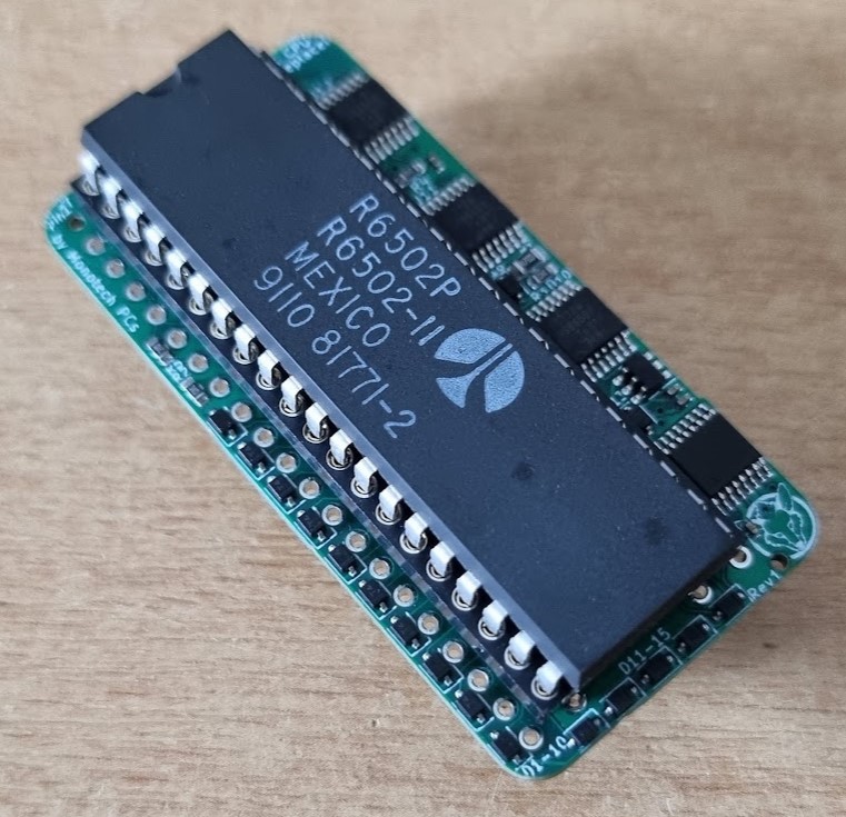
Main components on the MOS CPU Replacer
MOS CPU Replacer bill of materials (BOM)
67 components, 18 distinct parts — part numbers from the project's BOM.
| Qty | Part | Footprint | Refs |
|---|---|---|---|
| 1 | 6502 | DIP-40_W15.24mm_Socket | U1 |
| 5 | 595-SN74HCT245PWR HCT245 | TSSOP-20_4.4x6.5mm_P0.65mm | U2, U3, U4, U5, U6 |
| 2 | 595-SN74HCT273PWR HCT273 | TSSOP-20_4.4x6.5mm_P0.65mm | U7, U8 |
| 1 | 771-HCT138PW118 HCT138 | TSSOP-16_4.4x5mm_P0.65mm | U9 |
| 3 | 771-HCT126PW118 HCT126 | TSSOP-14_4.4x5mm_P0.65mm | U10, U11, U12 |
| 1 | 595-74LVC1G373DCKRG4 LVC1G373 | SOT-363_SC-70-6 | U13 |
| 1 | 6510/6510T/8501 | 6510_6510T_8501_Socket | J1 |
| 1 | 8502 | DIP-40_W15.24mm_Socket | J4 |
| 1 | Open for W65C02 | SolderJumper-2_P1.3mm_Bridged_RoundedPad1.0x1.5mm | JP1 |
| 6 | A | SolderJumper-2_P1.3mm_Open_RoundedPad1.0x1.5mm | JP2, JP8, JP14, JP15, JP19, JP22 |
| 3 | AB | SolderJumper-2_P1.3mm_Open_RoundedPad1.0x1.5mm | JP3, JP7, JP11 |
| 4 | B | SolderJumper-2_P1.3mm_Open_RoundedPad1.0x1.5mm | JP4, JP10, JP17, JP20 |
| 7 | C | SolderJumper-2_P1.3mm_Open_RoundedPad1.0x1.5mm | JP5, JP6, JP9, JP12, JP13, JP18, JP21 |
| 2 | BC | SolderJumper-2_P1.3mm_Open_RoundedPad1.0x1.5mm | JP16, JP23 |
| 17 | 241-1N4148WSR100001 1N4148W | D_SOD-323 | D1, D2, D3, D4, D5, D6, D7, D8 +9 |
| 7 | 187-CL05B104KP5NNWC 100nF | C_0402_1005Metric | C1, C2, C3, C4, C5, C6, C7 |
| 1 | 603-RC0805JR-07470RP 470 | R_0805_2012Metric | R1 |
| 4 | 603-RC0603FR-1310KL 10k | R_0603_1608Metric | R2, R3, R4, R5 |
MOS CPU Replacer design files
The KiCad project lives in the monotech/MOS_CPU_Replacer repository on GitHub; these links point at the commit this page was built from.
MOS CPU Replacer: common questions
How big is the MOS CPU Replacer PCB?
The MOS CPU Replacer measures 28.2 × 56 mm, has 4 copper layers and is 1.6 mm thick.
How many components are on the MOS CPU Replacer?
67 components, from 18 distinct parts, with part numbers taken from the project's own BOM. The full bill of materials is listed on this page.
Where can I download the MOS CPU Replacer design files?
From the monotech/MOS_CPU_Replacer repository on GitHub, which has the KiCad layout, the schematic and the BOM; the links under Design files point to each one.
Can I use the MOS CPU Replacer design in my own project?
The repository has no license, so all rights stay with monotech. Use it as a reference, and ask the author before reusing the design.
Similar boards
Expansion Card Retrofit
FrameworkComputer
24 × 27.3 mm5 parts2LCC-BY-4.01.1k
Rgb to hdmi
hoglet67
77 × 97 mm67 parts2LGPL-3.01.0k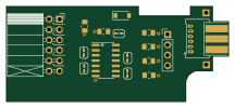
Buffer
53.9 × 23.2 mm13 parts2LGPL-3.01.0k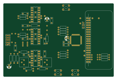
X1
121.9 × 81.3 mm51 parts2LGPL-3.01.0k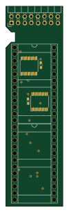
Amiga External
21.9 × 76.7 mm6 parts2LGPL-3.01.0k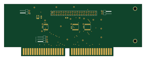
Videoslotadapter
152 × 57.6 mm13 parts2LGPL-3.01.0k