
LM53635-Q1-Wide-Input-DC-DC-Converter

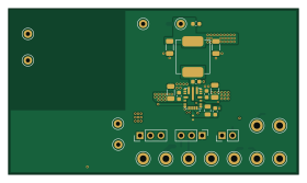
About the LM53635-Q1-Wide-Input-DC-DC-Converter PCB
LM53635-Q1-Wide-Input-DC-DC-Converter is an open source PCB design by NicheElectronics, published on GitHub. It is a 4-layer board measuring 70 × 40 mm, with 32 components from 20 distinct parts.
Other key parts include the LM536353QRNLRQ1. By type, the board carries 16 capacitors, 6 resistors, 4 inductors, 1 IC and 1 jumper.
It belongs with the power & battery and test & measurement designs in this gallery.
From the project
A four-layer, 5 V / 3.5 A design-target synchronous buck converter built around the Texas Instruments LM53635-Q1. The board is intended for a 6–36 V input and provides a choice of direct or EMI-filtered input paths for evaluating power-supply behavior.
A four-layer, 5 V / 3.5 A design-target synchronous buck converter built around the Texas Instruments LM53635-Q1. The board is intended for a 6–36 V input and provides a choice of direct or EMI-filtered input paths for evaluating power-supply behavior.
The 6–36 V range is this board's intended range. The IC's own operating limits and transient ratings are specified in the TI LM53635-Q1 datasheet; they should not be treated as a measured rating of the assembled board.
Main components on the LM53635-Q1-Wide-Input-DC-DC-Converter
LM53635-Q1-Wide-Input-DC-DC-Converter bill of materials (BOM)
32 components, 20 distinct parts — part numbers from the project's BOM.
| Qty | Part | Footprint | Refs |
|---|---|---|---|
| 1 | LM536353QRNLRQ1 | CONV_LMS3655MMRNLR | U1 |
| 2 | TestPoint | TestPoint_Keystone_5000-5004_Miniature | GND1, VIN1 |
| 2 | TestPoint | TestPoint_Keystone_5005-5009_Compact | GND2, GND3 |
| 1 | Reset Jumper | PinHeader_1x02_P2.54mm_Vertical | JP3 |
| 1 | 600 ohm | FB_HI2220P601R-10 | FB1 |
| 1 | ACM9070-701-2PL-TL01 | IND_ACM9070_TDK | L1 |
| 1 | 2.2UH 2.2uH | INDM5451X300N | L2 |
| 1 | 2.2UH 2.2uH | INDM8681X400N | L3 |
| 4 | 0.1UF 0.1uF | C_0603_1608Metric | C1, C9, C12, C13 |
| 2 | 10UF 10uF | C_1206_3216Metric | C2, C4 |
| 2 | 0.047UF 0.047uF | C_0603_1608Metric | C3, C6 |
| 2 | 4.7UF 4.7uF | C_1210_3225Metric | C5, C7 |
| 1 | 4.7UF 4.7uF | C_0805_2012Metric | C8 |
| 1 | 100UF 100uF | CP_Elec_10x10.5 | C10 |
| 1 | 0.47UF 0.47uF | C_0603_1608Metric | C11 |
| 2 | 22UF 22uF | C_1206_3216Metric | C14, C15 |
| 1 | 47UF 47uF | C_1210_3225Metric | C16 |
| 3 | 100K | R_0603_1608Metric | R1, R4, R6 |
| 2 | 0R | R_1206_3216Metric | R2, R3 |
| 1 | 3R | R_0603_1608Metric | R5 |
LM53635-Q1-Wide-Input-DC-DC-Converter design files
The KiCad project lives in the NicheElectronics/LM53635-Q1-Wide-Input-DC-DC-Converter repository on GitHub; these links point at the commit this page was built from.
LM53635-Q1-Wide-Input-DC-DC-Converter: common questions
How big is the LM53635-Q1-Wide-Input-DC-DC-Converter PCB?
The LM53635-Q1-Wide-Input-DC-DC-Converter measures 70 × 40 mm, has 4 copper layers and is 1.6 mm thick.
How many components are on the LM53635-Q1-Wide-Input-DC-DC-Converter?
32 components, from 20 distinct parts, with part numbers taken from the project's own BOM. The full bill of materials is listed on this page.
Where can I download the LM53635-Q1-Wide-Input-DC-DC-Converter design files?
From the NicheElectronics/LM53635-Q1-Wide-Input-DC-DC-Converter repository on GitHub, which has the KiCad layout, the schematic and the BOM; the links under Design files point to each one.
Can I use the LM53635-Q1-Wide-Input-DC-DC-Converter design in my own project?
The repository has no license, so all rights stay with NicheElectronics. Use it as a reference, and ask the author before reusing the design.
Similar boards
StackLink
gusmanb
52.3 × 10.5 mm5 parts2LGPL-3.05.0k
AnalyzerBoxPCB fork
52.7 × 47.9 mm54 parts4LGPL-3.05.0k
LevelShifter
28.3 × 39.8 mm21 parts2LGPL-3.05.0k
EinkPDA screen
TalismanDesign
95 × 54 mm27 parts2LApache-2.02.0k
Stack chan
stack-chan
50 × 50 mm33 parts2LApache-2.01.7k
Display Carrier
AxxAxx
35.6 × 58.2 mm5 parts2LGPL-3.01.7k