
Power circuit new

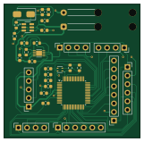
About the Power circuit new PCB
Power circuit new is an open source STM32 PCB design by Omkar1464, published on GitHub. It is a 2-layer board measuring 40.3 × 39.7 mm, with 32 components from 24 distinct parts.
Its main chip is the STM32G071RBT6, from the STM32 family. Other key parts include the SHT4x, MT3608 and MCP1640-I/MC. By type, the board carries 11 capacitors, 6 resistors, 4 ICs, 2 inductors, 1 battery holder and 1 diode.
It belongs with the rf & radio, power & battery and sensors designs in this gallery.
From the project
This repository contains the embedded firmware, circuit schematics, simulation models, and validation benchmarks for the Long Range Telemetry Module (Phase-I) designed for high-altitude drone and UAV/CanSat payload communication.
This repository contains the embedded firmware, circuit schematics, simulation models, and validation benchmarks for the Long Range Telemetry Module (Phase-I) designed for high-altitude drone and UAV/CanSat payload communication.
Operating under the severe resource constraints of an 8-bit ATmega328P microcontroller (16 MHz clock, 2 KB SRAM), the system implements a Direct Sequence Spread Spectrum (DSSS) / Code Division Multiple Access (CDMA) baseband transmitter alongside a discrete 433 MHz RF front-end architecture.
Main components on the Power circuit new
Power circuit new bill of materials (BOM)
32 components, 24 distinct parts.
| Qty | Part | Footprint | Refs |
|---|---|---|---|
| 1 | SHT4x | Sensirion_DFN-4_1.5x1.5mm_P0.8mm_SHT4x_NoCentralPad | U2 |
| 1 | MT3608 | SOT95P280X145-6N | U4 |
| 1 | STM32G071RBT6 | LQFP-64_7x7mm_P0.4mm | U5 |
| 1 | MCP1640-I/MC | DFN8_2x3MC_MCH | U6 |
| 1 | Battery_Cell | SolderWire-0.25sqmm_1x02_P4.2mm_D0.65mm_OD1.7mm_Relief2x | BT2 |
| 1 | GPIO_PINSET | PinSocket_1x08_P2.54mm_Vertical | GPIO_PINSET1 |
| 1 | GPS | PinSocket_1x04_P2.54mm_Vertical | GPS1 |
| 1 | PWM_OUT | PinSocket_1x04_P2.54mm_Vertical | PWM_OUT1 |
| 1 | SPI | PinSocket_1x06_P2.54mm_Vertical | SPI1 |
| 1 | SWD_PORT | PinSocket_1x05_P2.54mm_Vertical | SWD_PORT1 |
| 1 | Temp_ADC | PinSocket_1x06_P2.54mm_Vertical | Temp_ADC1 |
| 1 | UART1_SENSOR | PinSocket_1x04_P2.54mm_Vertical | UART1_SENSOR1 |
| 1 | SS14 | D_SMA | D2 |
| 1 | 4.7u | L_0603_1608Metric | L2 |
| 1 | 22u | L_0603_1608Metric | L4 |
| 5 | 100n | C_0603_1608Metric | C1, C2, C4, C5, C11 |
| 1 | 1u | C_0603_1608Metric | C3 |
| 3 | 10u | C_0603_1608Metric | C6, C8, C10 |
| 2 | 22u | C_0603_1608Metric | C7, C9 |
| 2 | 4.7k | R_0603_1608Metric | R1, R2 |
Show 4 more
| Qty | Part | Footprint | Refs |
|---|---|---|---|
| 1 | 976k | R_0603_1608Metric | R7 |
| 1 | 562k | R_0603_1608Metric | R8 |
| 1 | 750k | R_0603_1608Metric | R9 |
| 1 | 100k | R_0603_1608Metric | R10 |
Power circuit new design files
The KiCad project lives in the Omkar1464/Telemetry-Module-using-CDMA-Modulation repository on GitHub; these links point at the commit this page was built from.
Power circuit new: common questions
What microcontroller does the Power circuit new use?
The Power circuit new is built around the STM32G071RBT6, from the STM32 family.
How big is the Power circuit new PCB?
The Power circuit new measures 40.3 × 39.7 mm, has 2 copper layers and is 1.6 mm thick.
How many components are on the Power circuit new?
32 components, from 24 distinct parts. The full bill of materials is listed on this page.
Where can I download the Power circuit new design files?
From the Omkar1464/Telemetry-Module-using-CDMA-Modulation repository on GitHub, which has the KiCad layout and the schematic; the links under Design files point to each one.
Can I use the Power circuit new design in my own project?
The repository has no license, so all rights stay with Omkar1464. Use it as a reference, and ask the author before reusing the design.
Can I test firmware for the Power circuit new without the hardware?
Yes. HardLabs builds a simulation of the board from its netlist and BOM, so you can run and debug STM32 firmware against it before you order a PCB.
More boards in Telemetry-Module-using-CDMA-Modulation
Similar boards
 STM32
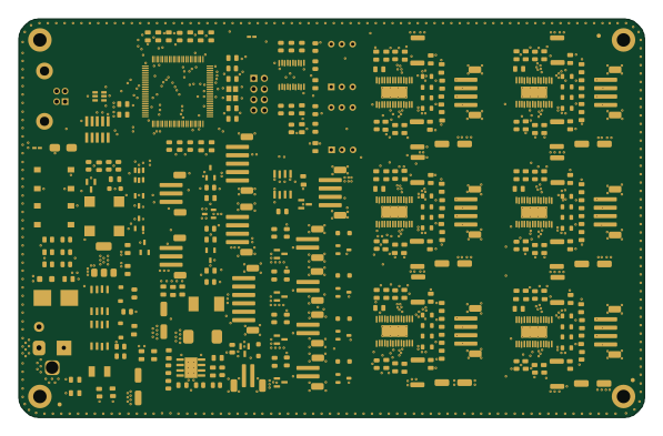
LumenPnP Motherboard
opulo-inc
149 × 95 mm296 parts4LCC-BY-SA-4.03.7k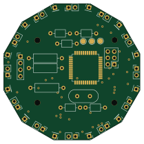 STM32
Base
google
52.3 × 52.3 mm36 parts2LApache-2.02.9k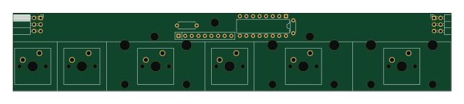 STM32
Type g
169 × 30 mm24 parts2LApache-2.02.9k STM32
Main panel
234 × 84 mm26 parts4LApache-2.02.9k STM32
Type a
150 × 30 mm14 parts2LApache-2.02.9k STM32
Type c
188 × 30 mm17 parts2LApache-2.02.9k