
PCB FujitoraBot2

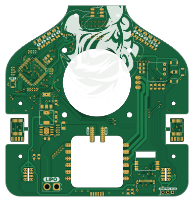
About the PCB FujitoraBot2
PCB FujitoraBot2 is an open source STM32 PCB design by OPRobots, published on GitHub under the AGPL-3.0 license. It is a 2-layer board measuring 95.6 × 100 mm, with 99 components from 44 distinct parts.
Its main chip is the STM32F405RGT6, from the STM32 family. Other key parts include the AS5040, MPU-6500 and LM1117MP-3.3. By type, the board carries 26 resistors, 20 capacitors, 14 diodes, 4 ICs, 4 jumpers and 4 switches.
It belongs with the power & battery and sensors designs in this gallery.
From the project
Versión 2 de FujitoraBot renovando el hardware después de 5 años: un pelín más rápido, con 24 sensores de línea, giroscopio MPU-6500 y diseño más modular.
Versión 2 de FujitoraBot renovando el hardware después de 5 años: un pelín más rápido, con 24 sensores de línea, giroscopio MPU-6500 y diseño más modular.
La documentación técnica completa está en docs/:
- Hardware — MCU, pinout, sensores, actuadores, chasis - Arquitectura Software — ISRs, DMA, prioridades, flujo - Sensores — 24 IR multiplexados, MPU-6500, filtros - Movimiento — Motores BLHeli, OneShot125, ventilador - Control PID — PID cascada, ant-windup, arranque - Menú — Navegación, perfiles, calibración/debug - Debug — USART, macroarray, modos de diagnóstico - Calibración — Giroscopio…
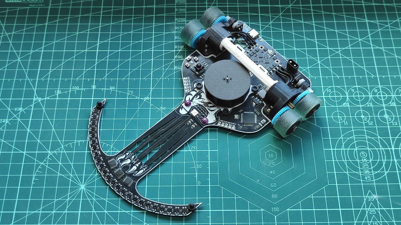
Main components on the PCB FujitoraBot2
PCB FujitoraBot2 bill of materials (BOM)
99 components, 44 distinct parts — part numbers from the project's BOM.
| Qty | Part | Footprint | Refs |
|---|---|---|---|
| 2 | AS5040 | SSOP-16_5.3x6.2mm_P0.65mm | IC1, IC2 |
| 1 | MPU-6500 | FujitoraBot2_giro_MPU6500 | U1 |
| 1 | LM1117MP-3.3 | SOT-223-3_TabPin2 | U2 |
| 1 | CRYSTAL_GND24 Crystal_GND24 | Crystal_SMD_TXC_7M-4Pin_3.2x2.5mm | Y1 |
| 1 | Conn_01x02_Female | XT30 connector | BATT_1 |
| 1 | MORRO1 | Fujitora_pads_morro | J1 |
| 1 | ~ | Bluetooth_BLE_1x1cm | BT1 |
| 5 | 0.1UF 0.1uF | C_0805_2012Metric | CR1, CR2, CR3, CR7, CR8 |
| 3 | 0.1UF 0.1uF | C_0402_1005Metric_Pad0.74x0.62mm_HandSolder | CR4, CR5, CR9 |
| 1 | 0.1UF 0.1uF | C_0805_2012Metric_Pad1.18x1.45mm_HandSolder | CR6 |
| 1 | 10UF 10uF | C_0805_2012Metric | CR10 |
| 1 | ~ | SOP8_with_gnd_pad | DC-DC1 |
| 1 | STM32F405RGT6 | LQFP-64_10x10mm_P0.5mm | DEIXAME_QUE_PENSE_1 |
| 1 | ESC_X4_15A ESC_x4_15A | Fujitora_ESC | ESC1 |
| 4 | SOLDERJUMPER_2_OPEN SolderJumper_2_Open | SolderJumper-2_P1.3mm_Open_Pad1.0x1.5mm | JP1, JP2, JP3, JP4 |
| 2 | Conn_01x04_Socket | FujitoraBot2_PCBmain_Encoder | J_ENC_1, J_ENC_2 |
| 2 | Conn_01x04_Pin | FujitoraBot2_PCBmodule_encoder | J_ENC_1_CONN1, J_ENC_2_CONN1 |
| 1 | Conn_01x06_Female | Fujitora_pads_ESC | J_ESC1 |
| 1 | Conn_01x03_Female | IR_Start | MODULO_START_STOP1 |
| 2 | Conn_01x03_Female | PinHeader_1x03_P2.54mm_Vertical | MOTOR_1, PIN_AUXILIAR1 |
Show 24 more
| Qty | Part | Footprint | Refs |
|---|---|---|---|
| 3 | SW_Push | SW_SPST_B3U-1000P | SW1, SW2, SW3 |
| 1 | SW_Reset | SW_SPST_B3U-1000P | SW4 |
| 1 | HRO-TYPE-C-31-M-12 | USB-C ST-Link USART | USB1 |
| 12 | LED | LED_0805_2012Metric | D1, D2, D3, D4, D5, D7, D8, D9 +4 |
| 1 | LED_RGB | LED_RGB_5050-6 | D6 |
| 1 | D | D_1206_3216Metric | D14 |
| 1 | L | L_Wuerth_HCM-7050 | L1 |
| 2 | 4.7UF 4.7uF | C_0402_1005Metric_Pad0.74x0.62mm_HandSolder | C1, C20 |
| 7 | 0.1UF 0.1uF | C_0402_1005Metric_Pad0.74x0.62mm_HandSolder | C2, C3, C7, C10, C11, C15, C17 |
| 2 | 2.2UF 2.2uF | C_0402_1005Metric_Pad0.74x0.62mm_HandSolder | C4, C9 |
| 1 | 20UF 20uF | C_0402_1005Metric_Pad0.74x0.62mm_HandSolder | C5 |
| 1 | 20PF 20pF | C_0402_1005Metric_Pad0.74x0.62mm_HandSolder | C6 |
| 2 | 1UF 1uF | C_0402_1005Metric_Pad0.74x0.62mm_HandSolder | C8, C12 |
| 2 | 1UF 1uF | C_0805_2012Metric | C13, C18 |
| 2 | 0.1UF 0.1uF | C_0805_2012Metric | C14, C19 |
| 1 | 0.01UF 0.01uF | C_0402_1005Metric_Pad0.74x0.62mm_HandSolder | C16 |
| 11 | 330 | R_0805_2012Metric | R1, R2, R3, R4, R5, R9, R10, R11 +3 |
| 3 | 330 | C_0402_1005Metric_Pad0.74x0.62mm_HandSolder | R6, R7, R8 |
| 3 | 47K 47k | R_0402_1005Metric_Pad0.72x0.64mm_HandSolder | R14, R17, R25 |
| 1 | 1K | R_0805_2012Metric | R16 |
| 5 | 47K | R_0805_2012Metric | R18, R19, R20, R23, R24 |
| 1 | 45K | R_0402_1005Metric_Pad0.72x0.64mm_HandSolder | R28 |
| 1 | 100K 100k | R_0402_1005Metric_Pad0.72x0.64mm_HandSolder | R29 |
| 1 | 60K 60k | R_0402_1005Metric_Pad0.72x0.64mm_HandSolder | R30 |
PCB FujitoraBot2 design files
The KiCad project lives in the OPRobots/FujitoraBot2 repository on GitHub; these links point at the commit this page was built from.
PCB FujitoraBot2: common questions
What microcontroller does the PCB FujitoraBot2 use?
The PCB FujitoraBot2 is built around the STM32F405RGT6, from the STM32 family.
How big is the PCB FujitoraBot2?
The PCB FujitoraBot2 measures 95.6 × 100 mm, has 2 copper layers and is 1.6 mm thick.
How many components are on the PCB FujitoraBot2?
99 components, from 44 distinct parts, with part numbers taken from the project's own BOM. The full bill of materials is listed on this page.
Where can I download the PCB FujitoraBot2 design files?
From the OPRobots/FujitoraBot2 repository on GitHub, which has the KiCad layout, the schematic and the BOM; the links under Design files point to each one.
Can I use the PCB FujitoraBot2 design in my own project?
Yes, under the terms of its AGPL-3.0 license, which OPRobots chose for the repository.
Can I test firmware for the PCB FujitoraBot2 without the hardware?
Yes. HardLabs builds a simulation of the board from its netlist and BOM, so you can run and debug STM32 firmware against it before you order a PCB.
More boards in FujitoraBot2
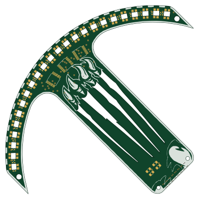
Similar boards
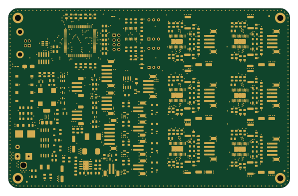 STM32
LumenPnP Motherboard
opulo-inc
149 × 95 mm296 parts4LCC-BY-SA-4.03.7k STM32
Base
google
52.3 × 52.3 mm36 parts2LApache-2.02.9k STM32
Type g
169 × 30 mm24 parts2LApache-2.02.9k STM32
Main panel
234 × 84 mm26 parts4LApache-2.02.9k STM32
Type a
150 × 30 mm14 parts2LApache-2.02.9k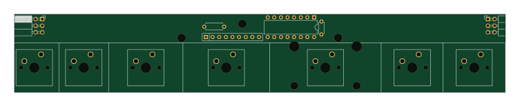 STM32
Type c
188 × 30 mm17 parts2LApache-2.02.9k