
Receive Path

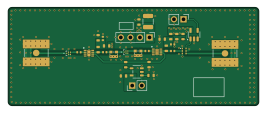
About the Receive Path PCB
Receive Path is an open source PCB design by oresat, published on GitHub under the GPL-3.0 license. It is a 4-layer board measuring 66.5 × 26 mm, with 34 components from 20 distinct parts.
Other key parts include the TQP3M9037, PAT1220-C-3DB-T5, SN74LVC1G32QDBVRQ1, PD2328J5050S2HF and LTC5505-1ES5#TRMPBF. By type, the board carries 12 capacitors, 7 ICs, 6 resistors, 5 connectors and 2 inductors.
It belongs with the rf & radio and iot & wireless designs in this gallery.
From the project
OreSat hardware for high speed data communications using 2.4 GHz WiFi.
This is hardware for the satellite only; please see the other repos if you're looking for the OreSat Live Handheld Ground Station or the Mini-OreSat testing platform for high altitude balloons.
We intend to use "ordinary WiFi" (IEEE 802.11b) as a high speed satellite communication system. What is not ordinary is that we run the radio under the amateur radio rules and regulations (FCC Part 97) and thus can increase power levels and antenna gains necessary to make the link budget work.
Main components on the Receive Path
Receive Path bill of materials (BOM)
34 components, 20 distinct parts — part numbers from the project's BOM.
| Qty | Part | Footprint | Refs |
|---|---|---|---|
| 2 | TQP3M9037 Qorvo | TQP3M9037 | U1, U5 |
| 2 | PAT1220-C-3DB-T5 PAT1220-C-3DB Susumu | PAT1220(0805) | U2, U4 |
| 1 | SN74LVC1G32QDBVRQ1 Texas Instruments | DBV5 SN74LVC1G3T2Q | U3 |
| 1 | PD2328J5050S2HF ANAREN | PD2328J5050S2HF | U6 |
| 1 | LTC5505-1ES5#TRMPBF LTC5505-1ES5 Analog Devices | TSOT-23-5 | U7 |
| 1 | 142-0711-201 Cinch Connectivity Solutions Johnson | SMA 142-0711-201 | J1 |
| 1 | 0022232041 Molex | PinHeader_1x04_P2.54mm_Vertical | J2 |
| 2 | 0022232021 Molex | PinHeader_1x02_P2.54mm_Vertical | J3, J5 |
| 1 | 142-0711-201 Conn_Coaxial_142-0711-201 Cinch Connectivity Solutions Johnson | SMA 142-0711-201 | J4 |
| 2 | QPQ1907SR Qorvo | QPQ1907SR | FL1, FL2 |
| 2 | 0603DC-18NXJRW 18nH Coilcraft | 0603-C-NOSILK | L1, L2 |
| 1 | GRM188Z71C225ME43J 2u2 Murata | 0603-C-NOSILK | C1 |
| 6 | GJM1555C1H150JB01D 15p Murata Electronics | 0402-C-NOSILK | C2, C4, C5, C8, C9, C10 |
| 1 | CGA6P1X7R1C226M250AC 22u TDK Corporation | C_1210_3225Metric | C3 |
| 2 | CGA3E1X7R1E105M080AE 1u TDK Corporation | 0603-C-NOSILK | C6, C11 |
| 2 | TMK107BJ104KAHT 100n TDK Corporation | 0603-C-NOSILK | C7, C12 |
| 2 | ERJ-3GEY0R00V 0 Panasonic Electronic Components | 0603-C-NOSILK | R1, R5 |
| 2 | ERJ-3EKF1002V 10k Panasonic Electronic Components | 0603-C-NOSILK | R2, R4 |
| 1 | ERJ-3GEYJ333V 33K Panasonic Electronic Components | 0603-C-NOSILK | R3 |
| 1 | ERJ-3GEY0R00V 10K Panasonic Electronic Components | 0603-C-NOSILK | R6 |
Receive Path design files
The KiCad project lives in the oresat/oresat-dxwifi-hardware repository on GitHub; these links point at the commit this page was built from.
Receive Path: common questions
How big is the Receive Path PCB?
The Receive Path measures 66.5 × 26 mm, has 4 copper layers and is 1.7702 mm thick.
How many components are on the Receive Path?
34 components, from 20 distinct parts, with part numbers taken from the project's own BOM. The full bill of materials is listed on this page.
Where can I download the Receive Path design files?
From the oresat/oresat-dxwifi-hardware repository on GitHub, which has the KiCad layout, the schematic and the BOM; the links under Design files point to each one.
Can I use the Receive Path design in my own project?
Yes, under the terms of its GPL-3.0 license, which oresat chose for the repository.
More boards in oresat-dxwifi-hardware
Similar boards

Radioberry preamp
pa3gsb
65 × 56 mm137 parts2LNo license675
Hat
65 × 56 mm81 parts2LNo license675
Radioberry juice
65 × 56 mm87 parts2LNo license675
ESP32
Chrismettal
66.4 × 48.1 mm20 parts2LCC-BY-SA-4.0446
ESP32
66.4 × 48.1 mm7 parts2LCC-BY-SA-4.0446
ESP32
66.4 × 48.1 mm20 parts2LCC-BY-SA-4.0446