
Driva x2

About the Driva x2 PCB
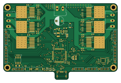
Driva x2 is an open source STM32 PCB design by owennewo, published on GitHub. It is a 4-layer board measuring 100 × 67 mm, with 147 components from 51 distinct parts.
Its main chip is the STM32F405RGTx, from the STM32 family. Other key parts include the mp2451dt, SN65HVD230, IFX007T and MPU-6050. By type, the board carries 61 capacitors, 52 resistors, 12 connectors, 10 ICs, 5 diodes and 3 switches.
It belongs with the robotics & motion and sensors designs in this gallery.
From the project
Experimental dual BLDC board for use with SimpleFOC
This board will cost about $200 for 5 units from JLCPCB. Include are gerber zip, BOM and POS. Designed in Kicad. This is pre-alpha quality e.g. I'm uncertain how much of it will work. I've tested v0.5 with motor and hall sensors on left motor and that worked.
- dual motor drivers using 3x btn8982 or ixf0007s - each motor has hall and spi port (untested) - prog (swd, swdio), can (untested), usart and i2c (untested) ports - ubg-otg (utested and without 5v attached) - onboard mpu6050 for 6 axis imu
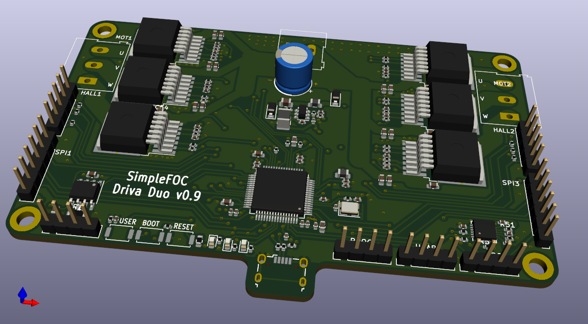
Main components on the Driva x2
Driva x2 bill of materials (BOM)
147 components, 51 distinct parts — part numbers from the project's BOM.
| Qty | Part | Footprint | Refs |
|---|---|---|---|
| 1 | mp2451dt | SOT-23-6 | U1 |
| 1 | SN65HVD230 | SOIC-8_3.9x4.9mm_P1.27mm | U2 |
| 1 | STM32F405RGTx | LQFP-64_10x10mm_P0.5mm | U3 |
| 6 | IFX007T | TO-263-7_TabPin8 | U4, U5, U6, U8, U9, U10 |
| 1 | MPU-6050 | InvenSense_QFN-24_4x4mm_P0.5mm | U7 |
| 1 | CONN_HALL_1 | PinHeader_1x05_P2.54mm_Vertical | J1 |
| 1 | CONN_PROG | PinHeader_1x04_P2.54mm_Vertical | J2 |
| 1 | CONN_USB_OTG | USB_Micro-B_Wuerth_629105150521 | J3 |
| 1 | CONN_MOT_1 | TerminalBlock_Altech_AK300-3_P5.00mm | J4 |
| 2 | CONN_SERIAL | PinHeader_1x04_P2.54mm_Vertical | J5, J12 |
| 1 | CONN_MOT_2 | TerminalBlock_Altech_AK300-3_P5.00mm | J6 |
| 1 | CONN_SPI_1 | PinHeader_1x06_P2.54mm_Vertical | J7 |
| 1 | CONN_SPI_2 | PinHeader_1x06_P2.54mm_Vertical | J8 |
| 1 | CONN_HALL_2 | PinHeader_1x05_P2.54mm_Vertical | J9 |
| 1 | CONN_CAN | PinHeader_1x04_P2.54mm_Vertical | J10 |
| 1 | CONN_PWR | TerminalBlock_Altech_AK300-2_P5.00mm | J11 |
| 1 | 16MHz | Crystal_SMD_3225-4Pin_3.2x2.5mm | HSE1 |
| 3 | push | SW_Push_SPST_NO_Alps_SKRK | SW1, SW2, SW3 |
| 2 | b5819w | D_SOD-123 | D1, D5 |
| 1 | RED | LED_0603_1608Metric | D2 |
Show 31 more
| Qty | Part | Footprint | Refs |
|---|---|---|---|
| 1 | GREEN | LED_0603_1608Metric | D3 |
| 1 | BLUE | LED_0603_1608Metric | D4 |
| 2 | 100 @ 100Mhz | L_0805_2012Metric | FB1, FB2 |
| 1 | 2.2uh | L_1210_3225Metric | L1 |
| 2 | 10u | C_0603_1608Metric | C1, C24 |
| 23 | 100n | C_0402_1005Metric | C2, C3, C4, C5, C6, C7, C8, C9 +15 |
| 1 | 10u | C_0402_1005Metric | C12 |
| 1 | 4.7u+ | C_0805_2012Metric | C13 |
| 2 | 10n | C_0402_1005Metric | C15, C61 |
| 2 | 12p | C_0402_1005Metric | C16, C17 |
| 3 | 2.2u | C_0603_1608Metric | C19, C22, C23 |
| 12 | 220n+ | C_0603_1608Metric | C26, C28, C31, C33, C36, C38, C44, C46 +4 |
| 6 | 100n+ | C_0603_1608Metric | C27, C32, C37, C45, C50, C55 |
| 6 | 1n | C_0402_1005Metric | C29, C34, C39, C47, C52, C57 |
| 1 | 2.2n | C_0402_1005Metric | C43 |
| 1 | 33p | C_0402_1005Metric | C59 |
| 1 | 1000u+ | CP_Radial_D8.0mm_P5.00mm | C60 |
| 3 | 22R | R_0402_1005Metric | R1, R2, R3 |
| 6 | 1K5 | R_0402_1005Metric | R4, R5, R6, R7, R8, R9 |
| 1 | 220 | R_0402_1005Metric | R10 |
| 1 | 2K2 | R_0603_1608Metric | R11 |
| 17 | 10k | R_0402_1005Metric | R12, R13, R17, R21, R22, R25, R26, R29 +9 |
| 1 | 120R+ | R_1206_3216Metric | R14 |
| 1 | 33K | R_0402_1005Metric | R15 |
| 1 | 3K3 | R_0402_1005Metric | R16 |
| 9 | 1k | R_0402_1005Metric | R18, R19, R20, R23, R27, R31, R35, R39 +1 |
| 6 | 510R | R_0402_1005Metric | R24, R28, R32, R36, R40, R44 |
| 1 | 300K | R_0402_1005Metric | R45 |
| 3 | 4.7k | R_0402_1005Metric | R46, R47, R48 |
| 1 | 120k | R_0402_1005Metric | R49 |
| 1 | 39k | R_0402_1005Metric | R50 |
Driva x2 design files
The KiCad project lives in the owennewo/driva-x2 repository on GitHub; these links point at the commit this page was built from.
Driva x2: common questions
What microcontroller does the Driva x2 use?
The Driva x2 is built around the STM32F405RGTx, from the STM32 family.
How big is the Driva x2 PCB?
The Driva x2 measures 100 × 67 mm, has 4 copper layers and is 1.6 mm thick.
How many components are on the Driva x2?
147 components, from 51 distinct parts, with part numbers taken from the project's own BOM. The full bill of materials is listed on this page.
Where can I download the Driva x2 design files?
From the owennewo/driva-x2 repository on GitHub, which has the KiCad layout and the BOM; the links under Design files point to each one.
Can I use the Driva x2 design in my own project?
The repository has no license, so all rights stay with owennewo. Use it as a reference, and ask the author before reusing the design.
Can I test firmware for the Driva x2 without the hardware?
Yes. HardLabs builds a simulation of the board from its netlist and BOM, so you can run and debug STM32 firmware against it before you order a PCB.
Similar boards
 STM32
STM32AxxSolder
AxxAxx
39 × 82.5 mm122 parts2LGPL-3.01.7k STM32
STM32AIOC
skuep
21 × 31.5 mm47 parts2LMIT1.4k STM32
STM32Ferris
pierrechevalier83
208.8 × 86.8 mm102 parts2LSHL-2.11.3k STM32
STM32Module 16S
stuartpittaway
71.1 × 89.6 mm113 parts4LCC-BY-NC-4.01.1k STM32
STM32Djinn
tzarc
192.3 × 150.5 mm216 parts2LCERN-OHL-S-2.0988 STM32
STM32Ghoul
228.6 × 79.4 mm163 parts2LCERN-OHL-S-2.0988