
PhotoSensors

About the PhotoSensors PCB
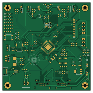
PhotoSensors is an open source AVR/Arduino PCB design by ParadigmHyperloop, published on GitHub under the Custom license license. It is a 2-layer board measuring 95 × 95 mm, with 94 components from 41 distinct parts.
Its main chip is the ATMEGA32U4RC-A, from the AVR/Arduino family. Other key parts include the MAX13432EETD, 7400 and NCP1117ST50T3GOSCT. By type, the board carries 48 resistors, 16 capacitors, 7 LEDs, 5 transistors, 3 ICs and 2 connectors.
It belongs with the sensors designs in this gallery.
From the project
All schematics and layouts in KiCad, plus some simulations
Owner: @edhurtig Status: Build Topic:** Research
In the most basic sense, this board is an Arduino with support for 2 modulated IR emitters and paired receivers. They are essentially smart IR proximity sensors.
These boards are intended to detect vertical strips (4" wide) that are placed every 100' on the hypertube walls. These strips are useful for navigation purposes and tell the pod where it is in the tube.
Main components on the PhotoSensors
PhotoSensors bill of materials (BOM)
94 components, 41 distinct parts — part numbers from the project's BOM.
| Qty | Part | Footprint | Refs |
|---|---|---|---|
| 1 | MAX13432EETD | SOIC-14_3.9x8.7mm_Pitch1.27mm | U1 |
| 1 | 7400 | SOIC-14_N | U2 |
| 1 | NCP1117ST50T3GOSCT | SOT-223 | U4 |
| 3 | FDN340P FDN340PCT-ND | SC-59 | Q1, Q2, Q4 |
| 1 | FDN340PCT | SC-59 | Q3 |
| 1 | Q_PMOS_SDG | SC-59 | Q5 |
| 1 | Crystal | Crystal_SMD_Abracon_ABM8G-4pin_3.2x2.5mm | Y1 |
| 2 | RJ45_LEDS | RJ45_8P8C_90DEG_LEDs | J1, J2 |
| 1 | 500mA | R_1812_HandSoldering | 500mA Fuse |
| 1 | ATMEGA32U4RC-A | QFN-44_7x7mm_Combined_TQFP-44_10x10mm_Pitch0.8mm | Atmega32U4 |
| 1 | CONN_IR0 | Pin_Header_Straight_1x02_Pitch2.54mm | IR 0 |
| 1 | CONN_IR1 | Pin_Header_Straight_1x02_Pitch2.54mm | IR 1 |
| 2 | RP500 | Potentiometer_Trimmer_Vishay_T73XW_Vertical | IR TRIM 0, IR TRIM 1 |
| 1 | CONN_PD0 | Pin_Header_Straight_1x03_Pitch2.54mm | RECV 0 |
| 1 | CONN_PD1 | Pin_Header_Straight_1x03_Pitch2.54mm | RECV 1 |
| 2 | CG0603MLC | R_0603 | RV4, RV5 |
| 1 | D0_ACT | LED_0603 | ACT 0 |
| 1 | D1_ACT | LED_0603 | ACT 1 |
| 1 | RS485_CONN | PhoenixContact_MC-G_04x3.50mm_Angled | AUX RS485 CONN |
| 1 | LED1 | LED_0603 | LED0 |
Show 21 more
| Qty | Part | Footprint | Refs |
|---|---|---|---|
| 1 | LED2 | LED_0603 | LED1 |
| 1 | LED3 | LED_0603 | LED2 |
| 1 | LED0 | LED_0603 | LED3 |
| 1 | D_VCOM | D_0603 | D9 |
| 1 | D_RST | D_0603 | D11 |
| 2 | 10N 10n | C_0603_HandSoldering | C1, C2 |
| 2 | 22U 22u | C_0805_HandSoldering | C3, C11 |
| 2 | 22P 22p | C_0603_HandSoldering | C4, C5 |
| 6 | 100N 100n | C_0603_HandSoldering | C6, C7, C9, C12, C15, C16 |
| 2 | 1u | C_0603_HandSoldering | C8, C10 |
| 2 | 10U 10u | C_0805_HandSoldering | C13, C14 |
| 13 | 0 | R_0603_HandSoldering | R1, R2, R3, R4, R16, R21, R23, R26 +5 |
| 2 | 20K 20k | R_0603_HandSoldering | R5, R6 |
| 16 | 1k | R_0603_HandSoldering | R7, R12, R13, R14, R17, R18, R19, R20 +8 |
| 2 | 220 | R_0603_HandSoldering | R8, R15 |
| 4 | DNS | R_0603_HandSoldering | R9, R10, R11, R47 |
| 1 | 470 | R_0603_HandSoldering | R22 |
| 2 | 120 | R_0603_HandSoldering | R24, R25 |
| 1 | 100K 100k | R_0603_HandSoldering | R35 |
| 5 | 10K 10k | R_0603_HandSoldering | R37, R38, R39, R42, R43 |
| 2 | 22R | R_0603_HandSoldering | R40, R41 |
PhotoSensors design files
The KiCad project lives in the ParadigmHyperloop/electrical repository on GitHub; these links point at the commit this page was built from.
PhotoSensors: common questions
What microcontroller does the PhotoSensors use?
The PhotoSensors is built around the ATMEGA32U4RC-A, from the AVR/Arduino family.
How big is the PhotoSensors PCB?
The PhotoSensors measures 95 × 95 mm, has 2 copper layers and is 1.6 mm thick.
How many components are on the PhotoSensors?
94 components, from 41 distinct parts, with part numbers taken from the project's own BOM. The full bill of materials is listed on this page.
Where can I download the PhotoSensors design files?
From the ParadigmHyperloop/electrical repository on GitHub, which has the KiCad layout and the BOM; the links under Design files point to each one.
Can I use the PhotoSensors design in my own project?
It is published under Custom license, which limits how it may be reused; read the license before building on it.
Can I test firmware for the PhotoSensors without the hardware?
Yes. HardLabs builds a simulation of the board from its netlist and BOM, so you can run and debug AVR/Arduino firmware against it before you order a PCB.
More boards in electrical
 Microchip SAM
Node
127 × 127 mm390 parts4LCustom license11
Thermoboard
315.8 × 53.1 mm340 parts2LCustom license11 AVR/Arduino
Motherboard
196.4 × 195.1 mm262 parts2LCustom license11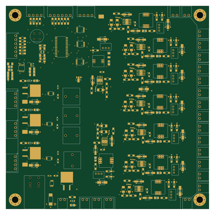
MainPowerBoard
177.8 × 177.8 mm259 parts2LCustom license11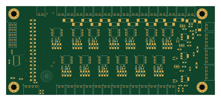
SSRBoard
209.3 × 88.9 mm213 parts2LCustom license11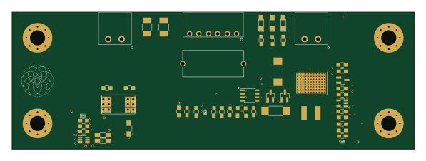
BatteryBoard
149 × 50.8 mm51 parts2LCustom license11
Tutorial
40 parts2LCustom license11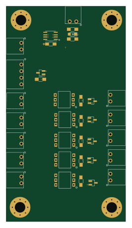
PusherProtectionBoard
63.5 × 114.3 mm35 parts2LCustom license11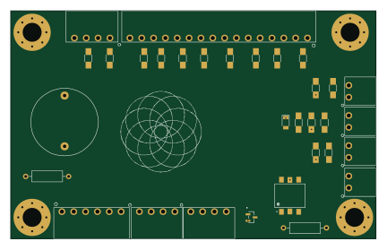
Led Board
108 × 67.3 mm32 parts2LCustom license11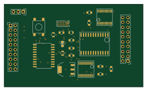
ClaremontJN
72.4 × 43.2 mm23 parts2LCustom license11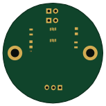
PHOTOBOARD
38.1 × 38.1 mm8 parts2LCustom license11
Similar boards
 AVR/Arduino
Magspoof
samyk
35 × 29 mm11 parts2LNo license4.2k AVR/Arduino
Redox keyboard
mattdibi
162.2 × 126.5 mm77 parts2LMIT2.0k AVR/Arduino
Labrador
espotek-org
36.8 × 34.7 mm75 parts2LNo license1.2k AVR/Arduino
ModuleV450
stuartpittaway
30 × 61.4 mm39 parts2LCC-BY-NC-4.01.1k AVR/Arduino
V4
30 × 50 mm38 parts2LCC-BY-NC-4.01.1k AVR/Arduino
Discipline
coseyfannitutti
304.9 × 122.8 mm170 parts2LCC-BY-NC-4.01.0k