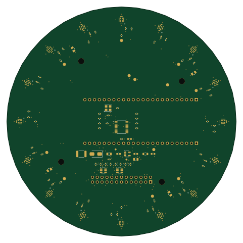
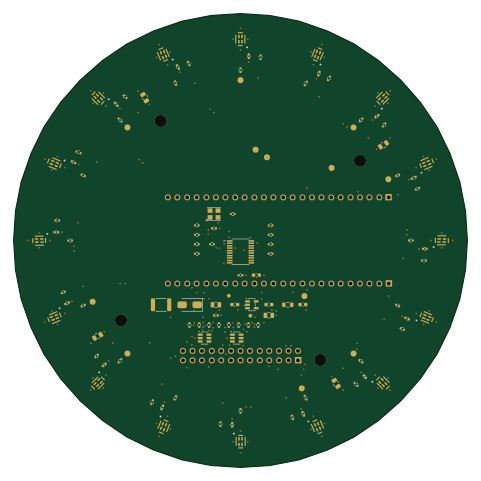
Microphone array v2

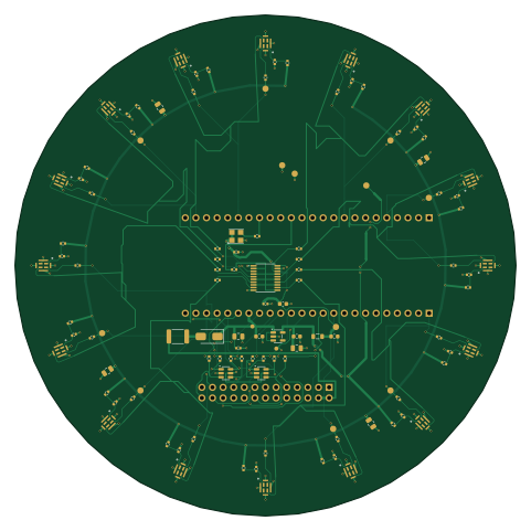
About the Microphone array v2 PCB
Microphone array v2 is an open source PCB design by pentolope, published on GitHub. It is a 4-layer board measuring 120 × 120 mm, with 103 components from 18 distinct parts.
Other key parts include the LP5907MFX-3.3/NOPB, SN74LVC244APWR and USBLC6-4SC6. By type, the board carries 16 microphones, 9 capacitors, 4 ICs, 2 resistors, 1 crystal and 1 fuse.
From the project
A 120 mm circular, four-layer KiCad 10 carrier for sixteen MSM261DHP006 PDM MEMS microphones running at 3.3 V. A socketed Sipeed Tang Nano 9K performs acquisition and decimation; a 2012 Raspberry Pi Model B collects the audio over SPI0 over a 26-way cable to the Pi's P1 header.
A 120 mm circular, four-layer KiCad 10 carrier for sixteen MSM261DHP006 PDM MEMS microphones running at 3.3 V. A socketed Sipeed Tang Nano 9K performs acquisition and decimation; a 2012 Raspberry Pi Model B collects the audio over SPI0 over a 26-way cable to the Pi's P1 header.
The sixteen acoustic ports sit on a 54.00 mm radius at 22.5 degree intervals, channel 0 on +X, numbered counter-clockwise viewed from the component side.
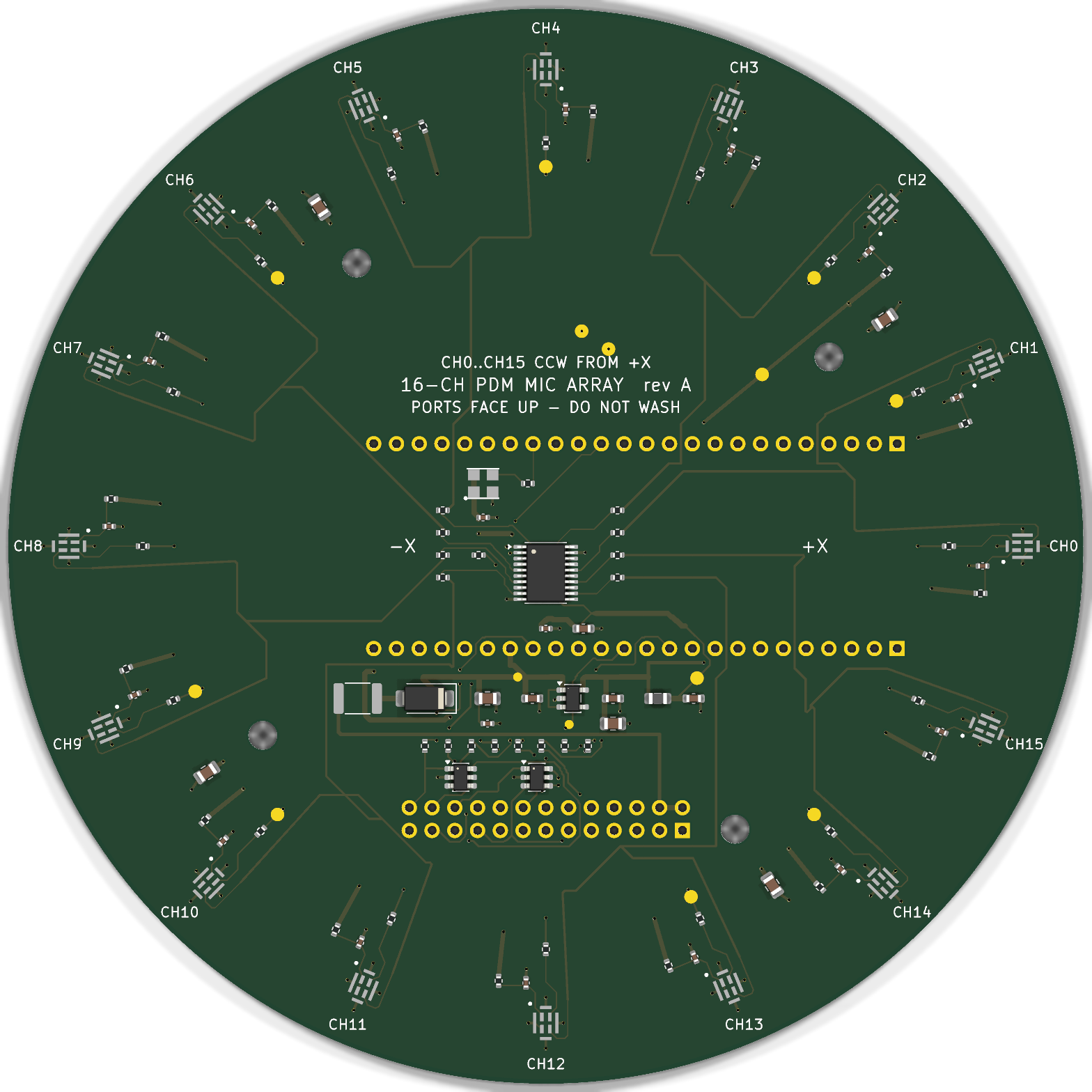
Main components on the Microphone array v2
Microphone array v2 bill of materials (BOM)
103 components, 18 distinct parts — part numbers from the project's BOM.
| Qty | Part | Footprint | Refs |
|---|---|---|---|
| 1 | LP5907MFX-3.3/NOPB LP5907MFX-3.3 Texas Instruments | SOT-23-5 | U1 |
| 1 | SN74LVC244APWR SN74LVC244A Texas Instruments | TSSOP-20_4.4x6.5mm_P0.65mm | U2 |
| 2 | USBLC6-4SC6 STMicroelectronics | SOT-23-6 | U3, U4 |
| 1 | OT322524.576MJBA4SL 24.576MHz YXC | Oscillator_SMD_YXC_3.2x2.5mm_4Pin | X1 |
| 4 | CL21A106KAYNNNE 10uF Samsung | C_0805_2012Metric | CB1, CB2, CB3, CB4 |
| 16 | CL05B104KO5NNNC 100nF Samsung | C_0402_1005Metric | CM1, CM2, CM3, CM4, CM5, CM6, CM7, CM8 +8 |
| 1 | JK-MSMD050-30 500mA Jinrui | Fuse_1812_4532Metric | F1 |
| 16 | MSM261DHP006 MEMSensing | MSM261DHP006_LGA-8_3x4mm_TopPort | MK1, MK2, MK3, MK4, MK5, MK6, MK7, MK8 +8 |
| 16 | 0402WGF330JTCE 33R UNI-ROYAL | R_0402_1005Metric | RC1, RC2, RC3, RC4, RC5, RC6, RC7, RC8 +8 |
| 16 | 0402WGF220JTCE 22R UNI-ROYAL | R_0402_1005Metric | RD1, RD2, RD3, RD4, RD5, RD6, RD7, RD8 +8 |
| 16 | 0402WGF1000TCE 100R UNI-ROYAL | R_0402_1005Metric | RV1, RV2, RV3, RV4, RV5, RV6, RV7, RV8 +8 |
| 1 | SS14 MDD | D_SMA | D1 |
| 1 | GZ2012D601TF 600R@100MHz Sunlord | L_0805_2012Metric | FB1 |
| 4 | CC0603KRX7R8BB105 1uF YAGEO | C_0603_1608Metric | C1, C2, C7, C9 |
| 1 | CL21A106KAYNNNE 10uF Samsung | C_0805_2012Metric | C3 |
| 1 | C2012X5R1C226KT000E 22uF TDK | C_0805_2012Metric | C4 |
| 3 | CL05B104KO5NNNC 100nF Samsung | C_0402_1005Metric | C5, C6, C8 |
| 2 | 0402WGF330JTCE 33R UNI-ROYAL | R_0402_1005Metric | R1, R2 |
Microphone array v2 design files
The KiCad project lives in the pentolope/MicrophoneArray_PCBA_V3 repository on GitHub; these links point at the commit this page was built from.
Microphone array v2: common questions
How big is the Microphone array v2 PCB?
The Microphone array v2 measures 120 × 120 mm, has 4 copper layers and is 1.6 mm thick.
How many components are on the Microphone array v2?
103 components, from 18 distinct parts, with part numbers taken from the project's own BOM. The full bill of materials is listed on this page.
Where can I download the Microphone array v2 design files?
From the pentolope/MicrophoneArray_PCBA_V3 repository on GitHub, which has the KiCad layout, the schematic and the BOM; the links under Design files point to each one.
Can I use the Microphone array v2 design in my own project?
The repository has no license, so all rights stay with pentolope. Use it as a reference, and ask the author before reusing the design.