
Solar telemetry

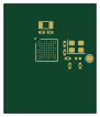
About the Solar telemetry PCB
Solar telemetry is an open source STM32 PCB design by pgupta9204, published on GitHub. It is a 4-layer board measuring 22 × 26 mm, with 38 components from 18 distinct parts.
Its main chip is the STM32WL55JCIx, from the STM32 family. Other key parts include the LIS2DW12TR and AEM10941-QFN. By type, the board carries 28 capacitors, 3 ICs, 3 inductors, 2 crystals and 2 resistors.
It belongs with the power & battery and rf & radio designs in this gallery.
From the project
An ultra-lightweight ($<8.0\text{g}$), perpetually energy-autonomous telemetry beacon engineered for avian wildlife conservation and asset tracking. Colloquially conceived as a "Solar AirTag", the system is architected from the ground up to replace heavy, battery-limited commerci
An ultra-lightweight ($<8.0\text{g}$), perpetually energy-autonomous telemetry beacon engineered for avian wildlife conservation and asset tracking. Colloquially conceived as a "Solar AirTag", the system is architected from the ground up to replace heavy, battery-limited commercial tags with a sub-GHz RF beacon powered by solar energy harvesting.
This project addresses this conservation bottleneck by engineering a complete telemetry solution under 8.0g total mass (with a bare-board electronic budget of <3.0g capable of indefinite operation via ambient solar energy.
Main components on the Solar telemetry
Solar telemetry bill of materials (BOM)
38 components, 18 distinct parts.
| Qty | Part | Footprint | Refs |
|---|---|---|---|
| 1 | STM32WL55JCIx | ST_UFBGA-73_5x5mm_Layout9x9_P0.5mm | U1 |
| 1 | LIS2DW12TR | LGA12R50P4X4_200X200X70 | U2 |
| 1 | AEM10941-QFN | QFN50P500X500X90-29N | U3 |
| 1 | 32MHz | Crystal_SMD_3225-4Pin_3.2x2.5mm | Y1 |
| 1 | 32.768kHz | Crystal_SMD_3215-2Pin_3.2x1.5mm | Y2 |
| 1 | 22µH | L_0805_2012Metric | L1 |
| 1 | 2.2µH | L_0805_2012Metric | L2 |
| 1 | 3.3nH | L_0402_1005Metric | L3 |
| 1 | 22µF | C_0805_2012Metric | C1 |
| 3 | 10µF | C_0603_1608Metric | C2, C4, C5 |
| 13 | 100nF | C_0402_1005Metric | C3, C6, C7, C8, C9, C11, C12, C13 +5 |
| 3 | 4.7µF | C_0603_1608Metric | C10, C19, C20 |
| 1 | 1µF | C_0402_1005Metric | C18 |
| 2 | 10pF | C_0402_1005Metric | C21, C22 |
| 2 | 6.8pF | C_0402_1005Metric | C23, C24 |
| 1 | 100pF | C_0402_1005Metric | C26 |
| 2 | 1.5pF | C_0402_1005Metric | C27, C28 |
| 2 | 1M | R_0402_1005Metric | R1, R2 |
Solar telemetry design files
The KiCad project lives in the pgupta9204/solar-telemetry repository on GitHub; these links point at the commit this page was built from.
Solar telemetry: common questions
What microcontroller does the Solar telemetry use?
The Solar telemetry is built around the STM32WL55JCIx, from the STM32 family.
How big is the Solar telemetry PCB?
The Solar telemetry measures 22 × 26 mm, has 4 copper layers and is 0.8 mm thick.
How many components are on the Solar telemetry?
38 components, from 18 distinct parts. The full bill of materials is listed on this page.
Where can I download the Solar telemetry design files?
From the pgupta9204/solar-telemetry repository on GitHub, which has the KiCad layout and the schematic; the links under Design files point to each one.
Can I use the Solar telemetry design in my own project?
The repository has no license, so all rights stay with pgupta9204. Use it as a reference, and ask the author before reusing the design.
Can I test firmware for the Solar telemetry without the hardware?
Yes. HardLabs builds a simulation of the board from its netlist and BOM, so you can run and debug STM32 firmware against it before you order a PCB.
Similar boards
 STM32
LumenPnP Motherboard
opulo-inc
149 × 95 mm296 parts4LCC-BY-SA-4.03.7k STM32
Type g
google
169 × 30 mm24 parts2LApache-2.02.9k STM32
Base
52.3 × 52.3 mm36 parts2LApache-2.02.9k STM32
Main panel
234 × 84 mm26 parts4LApache-2.02.9k STM32
Type a
150 × 30 mm14 parts2LApache-2.02.9k STM32
Type c
188 × 30 mm17 parts2LApache-2.02.9k