
Ignitor driver

About the Ignitor driver PCB
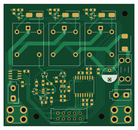
Ignitor driver is an open source PCB design by Queens-Rocket-Engineering-Team, published on GitHub. It is a 2-layer board measuring 70 × 65 mm, with 50 components from 29 distinct parts.
Other key parts include the LM4040C25FTA, TLV333IDBVR, OPA990IDBVR, AMC3330DWER and ACS724LLCTR-30AU-T. By type, the board carries 13 capacitors, 13 resistors, 6 ICs, 5 connectors, 5 diodes and 4 transistors.
It belongs with the power & battery designs in this gallery.
From the project
The GSE control node is the control PCB for GSE systems to integrate with launch control. This includes actuator control, fan control, and a load cell reading. This control node is used for control of the GSE equipment on the launch tower.
The GSE control node is the control PCB for GSE systems to integrate with launch control. This includes actuator control, fan control, and a load cell reading. This control node is used for control of the GSE equipment on the launch tower.
Control nodes use an ESP32S3-WROOM-1U microcontroller for systems control. This ESP32S3 communicates with an external control server to for remote control and data streaming over 2.4GHz WiFi. All commands are sent from the external server, as control nodes does not autonomously control any systems.
Main components on the Ignitor driver
Ignitor driver bill of materials (BOM)
50 components, 29 distinct parts.
| Qty | Part | Footprint | Refs |
|---|---|---|---|
| 2 | LM4040C25FTA LM4040DBZ-2.5 | SOT-23 | U1, U2 |
| 1 | TLV333IDBVR | SOT-23-5_HandSoldering | U3 |
| 1 | OPA990IDBVR | SOT-23-5_HandSoldering | U4 |
| 1 | AMC3330DWER AMC3330 | SOIC-16W_7.5x10.3mm_P1.27mm | U5 |
| 1 | ACS724LLCTR-30AU-T ACS724xLCTR-30AU | SOIC-8_3.9x4.9mm_P1.27mm | U6 |
| 1 | BSS83PH6327XTSA1 PMOS | SOT-23 | Q1 |
| 3 | BSS138 ON Semiconductor | SOT-23 | Q2, Q3, Q4 |
| 1 | Conn_02x05_Counter_Clockwise | Molex_Micro-Fit_3.0_43045-1012_2x05_P3.00mm_Vertical | J1 |
| 1 | AMT0440007DB0000G 24V_IN | AMT0440007DB0000G | J2 |
| 1 | AMT0440007DB0000G GND_IN | AMT0440007DB0000G | J3 |
| 1 | Ignitor | Molex_Mini-Fit_Jr_5566-02A_2x01_P4.20mm_Vertical | J4 |
| 1 | Lockout | Molex_Mini-Fit_Jr_5566-02A_2x01_P4.20mm_Vertical | J5 |
| 1 | Fuse | Fuseholder_Blade_Mini_Keystone_3568 | F1 |
| 3 | G5LE-1 DC24 | Relay_SPDT_Omron-G5LE-1 | K1, K2, K3 |
| 1 | BZT52C12-13-F 12V_Z | D_SOD-123 | D1 |
| 1 | SMCJ26A SMCJ26A-13-F | D_SMC | D2 |
| 3 | SK44BL-TP SK44BL | D_SMB_Handsoldering | D3, D4, D5 |
| 4 | 1nF | C_0805_2012Metric_Pad1.18x1.45mm_HandSolder | C1, C3, C7, C9 |
| 5 | 100nF | C_0805_2012Metric_Pad1.18x1.45mm_HandSolder | C2, C4, C10, C13, C14 |
| 3 | 1uF | C_0805_2012Metric_Pad1.18x1.45mm_HandSolder | C6, C8, C12 |
Show 9 more
| Qty | Part | Footprint | Refs |
|---|---|---|---|
| 1 | EEU-FR1H101B 100uF | CP_Radial_D8.0mm_P5.00mm | C11 |
| 1 | 0402WGF1000TCE 22k | R_0805_2012Metric_Pad1.20x1.40mm_HandSolder | R1 |
| 1 | 0402WGF1000TCE 10k | R_0805_2012Metric_Pad1.20x1.40mm_HandSolder | R2 |
| 1 | 0402WGF1000TCE 10k 0.1% | R_0805_2012Metric_Pad1.20x1.40mm_HandSolder | R3 |
| 1 | 0402WGF1000TCE 2.2k | R_0805_2012Metric_Pad1.20x1.40mm_HandSolder | R4 |
| 1 | 0402WGF1000TCE 30k 0.1% | R_0805_2012Metric_Pad1.20x1.40mm_HandSolder | R5 |
| 4 | 0402WGF1000TCE 100 | R_0805_2012Metric_Pad1.20x1.40mm_HandSolder | R6, R8, R9, R11 |
| 1 | 0402WGF1000TCE 500 | R_0603_1608Metric_Pad0.98x0.95mm_HandSolder | R7 |
| 3 | 0402WGJ0103TCE 100k | R_0805_2012Metric_Pad1.20x1.40mm_HandSolder | R10, R12, R13 |
Ignitor driver design files
The KiCad project lives in the Queens-Rocket-Engineering-Team/gse-control-node repository on GitHub; these links point at the commit this page was built from.
Ignitor driver: common questions
How big is the Ignitor driver PCB?
The Ignitor driver measures 70 × 65 mm, has 2 copper layers and is 1.6 mm thick.
How many components are on the Ignitor driver?
50 components, from 29 distinct parts. The full bill of materials is listed on this page.
Where can I download the Ignitor driver design files?
From the Queens-Rocket-Engineering-Team/gse-control-node repository on GitHub, which has the KiCad layout and the schematic; the links under Design files point to each one.
Can I use the Ignitor driver design in my own project?
The repository has no license, so all rights stay with Queens-Rocket-Engineering-Team. Use it as a reference, and ask the author before reusing the design.
More boards in gse-control-node
Similar boards
EinkPDA screen
TalismanDesign
95 × 54 mm27 parts2LApache-2.02.0k
Stack chan
stack-chan
50 × 50 mm33 parts2LApache-2.01.7k
Display Carrier
AxxAxx
35.6 × 58.2 mm5 parts2LGPL-3.01.7k
Module 16S PassiveBalanceAddOn
stuartpittaway
61 × 74 mm86 parts2LCC-BY-NC-4.01.1k
TemperaturePCB PANEL
116 × 75.5 mm178 parts2LCC-BY-NC-4.01.1k
ProgrammingAdapter
10.5 × 83 mm3 parts2LCC-BY-NC-4.01.1k